Information compression spring
BOSCH
9 423 613 821
9423613821
ZEXEL
156361-0700
1563610700
Rating:
Include in ###:
Cross reference number
Zexel num
Bosch num
Firm num
Name
156361-0700
9 423 613 821
COMPRESSION SPRING
C 14GQ SPRING;TIMER TIMER
C 14GQ SPRING;TIMER TIMER
Information:
Overview of Lubrication System
Flow of oilOil Pump, Relief Valve, and Oil Pressure Switch
Disassembly
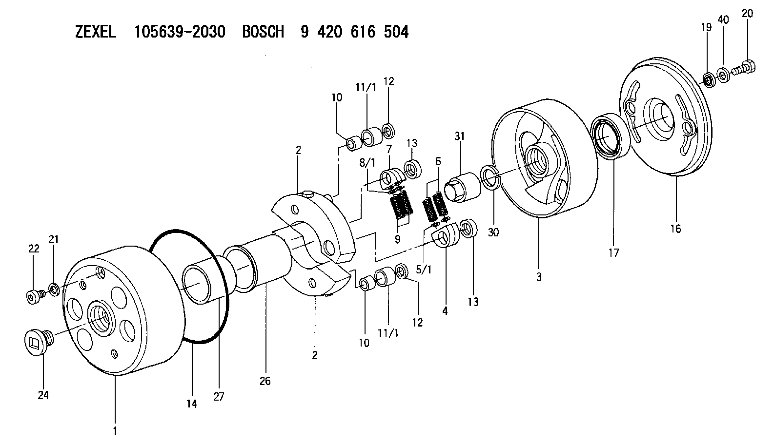
Removal sequence and points to check on oil pump(1) Oil filter(2) Oil pump(3) Gasket(4) Oil pump cover(5) Inner rotor(6) Outer rotor (the inner and outer rotors from a rotor assembly)(7) O-ring(8) Oil pump body(9) Relief valve(10) Oil pressure switch Key Points For Disassembly(1) Oil Pump
Remove the oil pump (parts (3) through (8) in the above illustration) as an assembly.
Removing oil pump(2) Oil Pressure Switch
Remove the switch using the Oil Pressure Switch Socket Wrench (MD998054).
Removing oil pressure switchInspection and Repair
(1) Oil Pump
(a) Using a thickness gauge, measure the clearance between the outer rotor and pump body. If the measurement exceeds the limit, replace the rotor assembly.Unit: mm (in.)
Measuring outer rotor-to-pump body clearance(b) Using a thickness gauge, measure the clearance between the outer rotor and the inner rotor. If the measurement exceeds the limit, replace the rotor assembly.Unit: mm (in.)
Measuring outer rotor-to-inner rotor clearance(c) Using a thickness edge and a thickness gauge, measure the clearance between the rotors and pump cover. If the measurement exceeds the limit, replace either the rotors or the pump body.Unit: mm (in.)
Measuring clearance between rotors and pump cover(2) Oil Pressure Switch
(a) Connect a tester (set to the ohm range) between the terminal and body of the oil pressure switch. There should be no continuity. If there is continuity, the switch is faulty and should be replaced.
Inspecting oil pressure switch(b) Insert a thin rod into the oil hole in the switch body. When the rod is then pushed in gently, there should be continuity between the switch body and terminal. If there is no continuity, the switch is faulty and should be replaced.(c) apply an air pressure of 49 kPa {0.5 kgf/cm2) (7.1 psi) to the switch through the oil hole. If there is continuity, the switch is normal. Simultaneously, check for air leakage. Any air leakage means that the diaphragm is broken and, therefore, the switch should be replaced.
Inspecting oil pressure switchAssembly
Point to note during reassembly of oil pumpPerform assembly by following the disassembly sequence in reverse: Key Points For Reassembly
Oil Pressure Switch
(a) Install the switch using the Oil Pressure Switch Socket Wrench (MD998054).(b) Before installation, apply sealant to the threads of the switch. (Use either Hermeseal H1 or ThreeBond 1104).
Installing Oil Pressure Switch
(a) Avoid applying sealant excessively to prevent it from reaching the end of the threads.(b Never tighten the switch to a torque exceeding specification.
Flow of oilOil Pump, Relief Valve, and Oil Pressure Switch
Disassembly
Removal sequence and points to check on oil pump(1) Oil filter(2) Oil pump(3) Gasket(4) Oil pump cover(5) Inner rotor(6) Outer rotor (the inner and outer rotors from a rotor assembly)(7) O-ring(8) Oil pump body(9) Relief valve(10) Oil pressure switch Key Points For Disassembly(1) Oil Pump
Remove the oil pump (parts (3) through (8) in the above illustration) as an assembly.
Removing oil pump(2) Oil Pressure Switch
Remove the switch using the Oil Pressure Switch Socket Wrench (MD998054).
Removing oil pressure switchInspection and Repair
(1) Oil Pump
(a) Using a thickness gauge, measure the clearance between the outer rotor and pump body. If the measurement exceeds the limit, replace the rotor assembly.Unit: mm (in.)
Measuring outer rotor-to-pump body clearance(b) Using a thickness gauge, measure the clearance between the outer rotor and the inner rotor. If the measurement exceeds the limit, replace the rotor assembly.Unit: mm (in.)
Measuring outer rotor-to-inner rotor clearance(c) Using a thickness edge and a thickness gauge, measure the clearance between the rotors and pump cover. If the measurement exceeds the limit, replace either the rotors or the pump body.Unit: mm (in.)
Measuring clearance between rotors and pump cover(2) Oil Pressure Switch
(a) Connect a tester (set to the ohm range) between the terminal and body of the oil pressure switch. There should be no continuity. If there is continuity, the switch is faulty and should be replaced.
Inspecting oil pressure switch(b) Insert a thin rod into the oil hole in the switch body. When the rod is then pushed in gently, there should be continuity between the switch body and terminal. If there is no continuity, the switch is faulty and should be replaced.(c) apply an air pressure of 49 kPa {0.5 kgf/cm2) (7.1 psi) to the switch through the oil hole. If there is continuity, the switch is normal. Simultaneously, check for air leakage. Any air leakage means that the diaphragm is broken and, therefore, the switch should be replaced.
Inspecting oil pressure switchAssembly
Point to note during reassembly of oil pumpPerform assembly by following the disassembly sequence in reverse: Key Points For Reassembly
Oil Pressure Switch
(a) Install the switch using the Oil Pressure Switch Socket Wrench (MD998054).(b) Before installation, apply sealant to the threads of the switch. (Use either Hermeseal H1 or ThreeBond 1104).
Installing Oil Pressure Switch
(a) Avoid applying sealant excessively to prevent it from reaching the end of the threads.(b Never tighten the switch to a torque exceeding specification.
Have questions with 156361-0700?
Group cross 156361-0700 ZEXEL
156361-0700
9 423 613 821
COMPRESSION SPRING