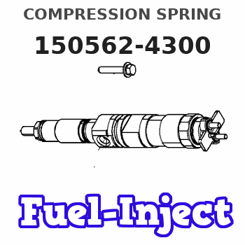
Information compression spring
BOSCH
9 431 610 328
9431610328
ZEXEL
150562-4300
1505624300
ISUZU
8941741410
8941741410

Rating:
Compare Prices: .
As an associate, we earn commssions on qualifying purchases through the links below
$46.89
04 May 2022
US: EFI Equipment and Pa
SPRING FOR ALLIS-CHALMERS: 150562-4300
Parts Express ALLIS-CHALMERS || All Brand new & rebuilt items comes with 1 year warranty. || SPRING. Category: ALLIS-CHALMERS FORKLIFT PARTS. This part can also be found under the following part numbers: ACDK150562-4300 150562-4300 ALLIS CHALMERS/TUSK AC DK150562-4300 ALLIS CHALMERS/TUSKDK150562-4300 ACDK1505624300 AC DK1505624300 DK150562-4300 ALLIS CHALMERS/TUSK DK1505624300 ALLIS CHALMERS/TUSKDK1505624300 DK1505624300. All Brand new & rebuilt items comes with 1 year warranty.
Parts Express ALLIS-CHALMERS || All Brand new & rebuilt items comes with 1 year warranty. || SPRING. Category: ALLIS-CHALMERS FORKLIFT PARTS. This part can also be found under the following part numbers: ACDK150562-4300 150562-4300 ALLIS CHALMERS/TUSK AC DK150562-4300 ALLIS CHALMERS/TUSKDK150562-4300 ACDK1505624300 AC DK1505624300 DK150562-4300 ALLIS CHALMERS/TUSK DK1505624300 ALLIS CHALMERS/TUSKDK1505624300 DK1505624300. All Brand new & rebuilt items comes with 1 year warranty.
Include in ###:
Cross reference number
Zexel num
Bosch num
Firm num
Name
150562-4300
9 431 610 328
8941741410 ISUZU
COMPRESSION SPRING
C 53PZ SPRING;NOZZLE NH parts NH
C 53PZ SPRING;NOZZLE NH parts NH
150562-4300
9 431 610 328
ME705421 MITSUBISHI
COMPRESSION SPRING
C 53PZ SPRING;NOZZLE NH parts NH
C 53PZ SPRING;NOZZLE NH parts NH
150562-4300
9 431 610 328
1662254T00 NISSAN
COMPRESSION SPRING
C 53PZ SPRING;NOZZLE NH parts NH
C 53PZ SPRING;NOZZLE NH parts NH
150562-4300
9 431 610 328
1661589TA2 NISSAN
COMPRESSION SPRING
A C 53PZ SPRING;NOZZLE NH parts NH
A C 53PZ SPRING;NOZZLE NH parts NH
150562-4300
9 431 610 328
1662254T00 NISSAN-DIESEL
COMPRESSION SPRING
C 53PZ SPRING;NOZZLE NH parts NH
C 53PZ SPRING;NOZZLE NH parts NH
150562-4300
9 431 610 328
SL0124704 MAZDA
COMPRESSION SPRING
C 53PZ SPRING;NOZZLE NH parts NH
C 53PZ SPRING;NOZZLE NH parts NH
150562-4300
9 431 610 328
62153430040 ISEKI
COMPRESSION SPRING
C 53PZ SPRING;NOZZLE NH parts NH
C 53PZ SPRING;NOZZLE NH parts NH
150562-4300
9 431 610 328
2286320508 FUJI-HEAVY
COMPRESSION SPRING
C 53PZ SPRING;NOZZLE NH parts NH
C 53PZ SPRING;NOZZLE NH parts NH
Information:
Illustration 5 g01943178
Coil without debris
Illustration 6 g03351850
(2) Debris on the coil
Inspect the coil for debris.The debris will be visible in the form of metal shavings on the coil. Refer to Illustration. If the coil is covered in soot, use a clean magnet to locate the debris.Note: DO NOT use high-pressure fluid or other cleaning solvents. Debris may be lost during cleaning.
If debris is present and/or an injector is inoperable perform the remaining Steps that are in Special Instruction, REHS3819, "Procedure for Troubleshooting and Cleaning the Oil Rail System for the Hydraulic Electronic Unit Injector (HEUI)". Ensure that the system is flushed through six injector bores, two large and six small plugs.
Illustration 7 g03344174
Close-up view of cylinder head (3) 9S-8003 Plug (4) 214-7567 O-Ring Seal (5) 205-3079 Adapter , and sensor location (if needed)
Cylinder heads that were manufactured prior to January 2006 must relocate the HEUI pressure sensor. Refer to Illustration 7 for the proper location for the HEUI pressure sensor.
Install plug (3) with seal (4) into the port.
Install sensor into the cylinder head at cylinder number 4.
Install sensor into the cylinder head at cylinder number 4, utilizing the following components: 205-3079 Adapter , 214-7567 O-Ring Seal and 214-7568 O-Ring Seal
Illustration 8 g03355201
(6) Fuel pump (7) Gear
Install fuel pump (6) .
Illustration 9 g03345875
(6) Fuel pump (8) Bolts
Position fuel pump (6) and install bolts (8) through the front housing.
Illustration 10 g03355149
View of 242-7032 Engine Oil Lines Gp (9) 6V-9850 Elbow (10) 228-7089 O-Ring Seal (11) 378-8430 Tube As (12) 8C-8988 Elbow
Illustration 11 g03355176
Proper tightening sequence for oil line fittings
Install elbow (9) with o-ring seal (10) onto the fuel pump. Do not tighten the fitting. Refer to Illustration 10
Install elbow (12) with o-ring seal (10) onto the cylinder head port. Do not tighten the fitting.
Install tube assembly (11).
Tighten the fittings to a torque of 45 N m (33 lb ft), that are shown in Illustration 11 using the proper torque sequence.
Illustration 12 g03345035
View of 388-2124 Unit Injection Hydraulic Pump and Mounting Gp (10) 228-7089 O-Ring Seal (13) 068-4174 Elbow (14) 238-5081 O-Ring Seal (15) 6V-8724 Elbow (16) 214-7568 O-Ring Seal (17) 6V-8636 Connector (18) 030-7950 Elbow (19) 238-5082 O-Ring Seal (20) 387-9500 Tube As (21) 387-7159 Tube As (22) 2R-6806 O-Ring Connector (23) 384-0678 or 20R-1636 Unit Injector Hydraulic Pump Gp (24) 9S-8004 Plug
Use the following Steps in order to install the fittings and plugs from the current pump to the new pump. Refer to Illustration 12 for the proper location of the fittings and plugs.
Install the fitting (10) with o-ring seal (16, 17) .
Install fitting (22) with o-ring seal (16) .
Install plug (24) with o-ring seal (16)
Install elbow (15) with o-ring seal (10, 16) onto the fuel pump.
Connect the harness assembly to the connector of the fuel pump.
Install elbow (13) with o-ring seal (14). Refer to Illustration 12
Have questions with 150562-4300?
Group cross 150562-4300 ZEXEL
Isuzu
150562-4300
9 431 610 328
8941741410
COMPRESSION SPRING
Mitsubishi
150562-4300
9 431 610 328
ME705421
COMPRESSION SPRING
Nissan
150562-4300
9 431 610 328
1662254T00
COMPRESSION SPRING
150562-4300
9 431 610 328
1661589TA2
COMPRESSION SPRING
Nissan-Diesel
150562-4300
9 431 610 328
1662254T00
COMPRESSION SPRING
Mazda
150562-4300
9 431 610 328
SL0124704
COMPRESSION SPRING
Iseki
150562-4300
9 431 610 328
62153430040
COMPRESSION SPRING
Fuji-Heavy
150562-4300
9 431 610 328
2286320508
COMPRESSION SPRING


