Information compression spring
BOSCH
9 461 610 126
9461610126
ZEXEL
146232-0220
1462320220
ISUZU
8942291640
8942291640
Rating:
Compare Prices: .
As an associate, we earn commssions on qualifying purchases through the links below

$11.99
28 Jun 2022
LV: Gear245
Bosch 9461610126 Compression Spring
BOSCH
BOSCH
Include in ###:
Cross reference number
Zexel num
Bosch num
Firm num
Name
146232-0220
9 461 610 126
8942291640 ISUZU
COMPRESSION SPRING
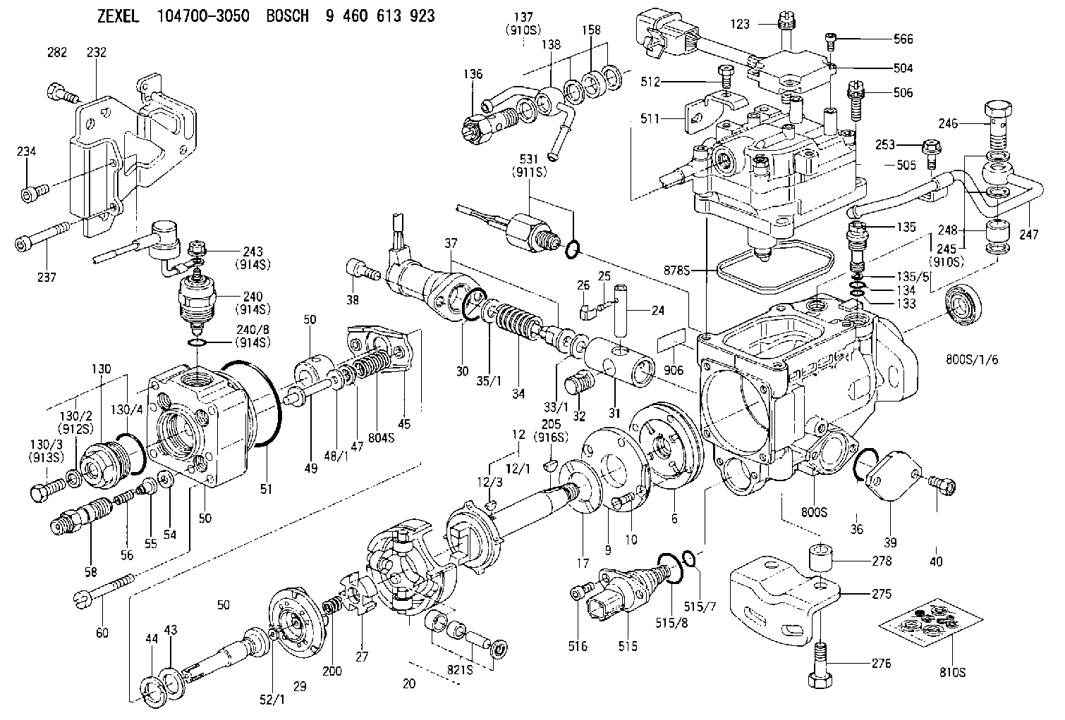
C 11FV SPRING;PLUNGER KIT parts(VE) Others
C 11FV SPRING;PLUNGER KIT parts(VE) Others
146232-0220
9 461 610 126
16770R8100 NISSAN
COMPRESSION SPRING
C 11FV SPRING;PLUNGER KIT parts(VE) Others
C 11FV SPRING;PLUNGER KIT parts(VE) Others
146232-0220
9 461 610 126
1676723G00 NISSAN
COMPRESSION SPRING
A C 11FV SPRING;PLUNGER KIT parts(VE) Others
A C 11FV SPRING;PLUNGER KIT parts(VE) Others
146232-0220
9 461 610 126
16770R8100 NISSAN-DIESEL
COMPRESSION SPRING
C 11FV SPRING;PLUNGER KIT parts(VE) Others
C 11FV SPRING;PLUNGER KIT parts(VE) Others
146232-0220
9 461 610 126
1676723G00 NISSAN-DIESEL
COMPRESSION SPRING
A C 11FV SPRING;PLUNGER KIT parts(VE) Others
A C 11FV SPRING;PLUNGER KIT parts(VE) Others
146232-0220
9 461 610 126
093324074 MAZDA
COMPRESSION SPRING
C 11FV SPRING;PLUNGER KIT parts(VE) Others
C 11FV SPRING;PLUNGER KIT parts(VE) Others
Information:
The 169-3374 Injector Sleeve Removal Group is used to remove the brass injector sleeves on 3176 and 3176B Engines, only. This tool group is used with the 9U-6860 Sleeve Replacement Group . The tool group eliminates the tapping and threading operation of the current 9U-6860 Sleeve Replacement Group . The benefits of this method of sleeve removal are easier sleeve removal and little debris that could enter the engine. This tool group uses a crimping die and captured stud similar to the current 3100 Sleeve Removal Tool. This tool group can be used with the cylinder head either on or off the engine.Additional Contact Information
For additional product support questions concerning this tool, contact the Dealer Service Tools Hotline at:USA: 1-800-542-8665, Option 1International: 1-309-578-7372Injector Sleeve Removal
Remove the rocker arms from the cylinder being repaired.
Remove the injector.
Illustration 4 g02888499
Put Sleeve Stud (3) into Injector Sleeve
Drop 142-8280 Sleeve Stud (3) into the injector sleeve and ensure that stud is resting at the bottom of the injector sleeve. The flat disc part of the sleeve stud should be below the top edge of the brass sleeve.
Illustration 5 g02888500
Insert Crimping Swage (9) Into Bore And Over Sleeve Stud (3)
Apply a light coating of grease to the inside cutting edge of crimping swage (9) and insert into the injector bore. Make sure that the tool is resting on the top edge of the brass sleeve by turning or "wiggling" slightly. It is possible for the tool to rest on the casting ledge (indicated by the arrow) in the cylinder head. The threads of sleeve stud (3) should go into the center hole of crimping swage (9), as shown in Figure 5.
Illustration 6 g02888508
Drive Crimping Swage (9) Down Into Injector Sleeve
Using a large hammer, strike the top of crimping swage (9) firmly and squarely. Drive down into the injector bore until the bottom slot is level with the top deck of the cylinder head, as shown in Figure 6.
Illustration 7 g02888509
Remove Driving Swage (9) With Crows Foot Pry Bar (12)
Remove the crimping swage from the injector bore. If the tool is stuck in the bore, use a crows foot pry bar (12) in the slot to work out the tool. Many times there will be a small amount of brass caught between crimping swage (9) and the injector bore causing the tool to stick. When the tool is removed, the top of the brass sleeve should be rolled over, trapping sleeve stud (3) inside the injector sleeve.Note: The sharp edge of crimping swage (9) must remain sharp and free of nicks or damage. This tool may be resharpened only on the inside cutting edge. Any sharpening procedure that reduces the OD of the cutting edge will result in poor tool performance and tool sticking.
Illustration 8 g02888517
Insert Sleeve Jaw (4)
Insert 151-4833 Sleeve Jaw (4) into the injector bore. The sharp edge of the sleeve jaw is designed to lock the rolled-over brass material between the sleeve stud and the sleeve jaw. The sleeve stud is then prevented from
Have questions with 146232-0220?
Group cross 146232-0220 ZEXEL
Isuzu
146232-0220
9 461 610 126
8942291640
COMPRESSION SPRING
Nissan
146232-0220
9 461 610 126
16770R8100
COMPRESSION SPRING
146232-0220
9 461 610 126
1676723G00
COMPRESSION SPRING
Nissan-Diesel
146232-0220
9 461 610 126
16770R8100
COMPRESSION SPRING
146232-0220
9 461 610 126
1676723G00
COMPRESSION SPRING
Mazda
146232-0220
9 461 610 126
093324074
COMPRESSION SPRING