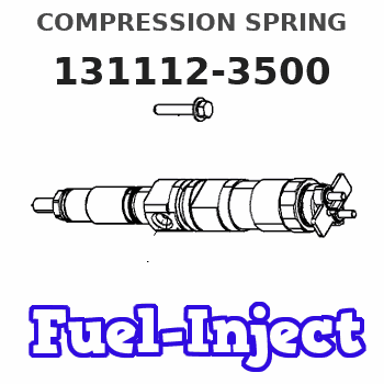
Information compression spring
BOSCH
9 411 611 081
9411611081
ZEXEL
131112-3500
1311123500
ISUZU
1156430030
1156430030

Rating:
Compare Prices: .
As an associate, we earn commssions on qualifying purchases through the links below
Beta 1 Filters Replacement Air Filter Compatible with 1311123500 / US AIR Compressor
Beta 1 Filters Filter compatible with 1311123500 / US AIR COMPRESSOR || Meets or exceeds OEM Standards || All filters are manufactured by an ISO Certified company || Designed to capture and retain dust and debris from the air. || Avoid unnecessary downtime and costly repairs with premium replacements
Beta 1 Filters Filter compatible with 1311123500 / US AIR COMPRESSOR || Meets or exceeds OEM Standards || All filters are manufactured by an ISO Certified company || Designed to capture and retain dust and debris from the air. || Avoid unnecessary downtime and costly repairs with premium replacements
$219.00
10 Aug 2024
CN: FILME Compressor Par
1311123500 Air Filter Element Suitable for Air Compressor Replacement 1311-1235-00
FILME 1311123500 Air Filter Element Suitable for US Air Compressor Replacement 1311-1235-00 || All New, Made in the USA.Warranty 3 Months. || Pictures are for participation only, Please check the part number match before ordering. || Provide Any Technical Support Services for Your Compressor.
FILME 1311123500 Air Filter Element Suitable for US Air Compressor Replacement 1311-1235-00 || All New, Made in the USA.Warranty 3 Months. || Pictures are for participation only, Please check the part number match before ordering. || Provide Any Technical Support Services for Your Compressor.
Include in ###:
Cross reference number
Zexel num
Bosch num
Firm num
Name
131112-3500
9 411 611 081
1156430030 ISUZU
COMPRESSION SPRING
C 14FL SPRING;D.V. parts(A,AD) Others
C 14FL SPRING;D.V. parts(A,AD) Others
131112-3500
9 411 611 081
ME704009 MITSUBISHI
COMPRESSION SPRING
C 14FL SPRING;D.V. parts(A,AD) Others
C 14FL SPRING;D.V. parts(A,AD) Others
131112-3500
9 411 611 081
1677689TA1 NISSAN
COMPRESSION SPRING
C 14FL SPRING;D.V. parts(A,AD) Others
C 14FL SPRING;D.V. parts(A,AD) Others
131112-3500
9 411 611 081
TF0113V22 MAZDA
COMPRESSION SPRING
C 14FL SPRING;D.V. parts(A,AD) Others
C 14FL SPRING;D.V. parts(A,AD) Others
Information:
Injection timing adjustment shim
Adjusting injection timing(3) Alternative Adjustment/Inspection ProcedureThe injection timing adjustment/inspection procedure in which the delivery valve is removed allows the flow of fuel to be verified clearly, but removing the delivery valve can allow dirt to enter the fuel system. With the procedure described below, it is possible to check the injection timing without removing the delivery valve.(a) Disconnect injection pipe No. 1 from the nozzle holder.
Disconnecting injection pipe No. 1(b) Slowly turn the crankshaft clockwise, and note the position of the IT mark at the point in time when fuel emerges from the end of the pipe. The timing indicated by the IT mark is retarded by approximately 1° relative to the actual injection timing, so this 1° difference must be taken into account in the shim selection. Air-bleed the fuel system before turning the crankshaft. 4. Injectors
4.1 Removal
Removing and installing injectors1 Fuel injection pipe2 Injector holder3 Injector4 Gasket
The fuel injection pipe nut should be tightened to the specified torque using a tool specially designed for the purpose.
4.2 Inspection and AdjustmentCheck each injector for the following points. If the result is not satisfactory, either repair or replace it according to conditions.(1) Injector Valve Opening Pressure(a) Install an injector on an injector tester. Move the handle up and down repeatedly to remove air from the injector.(b) While observing the pressure gauge, operate the handle at a rate of approximately one stroke per second. Record the reading.
Testing injector valve opening pressure The needle of the gauge moves slowly toward the higher pressure side and then wobbles while injection is taking place. Injector valve opening pressure corresponds to a pressure at which the gauge needle starts wobbling.(c) If the reading on the gauge does not correspond to the specified injector valve opening pressure of 21.6+10 MPa {220+100kgf/cm2} (3130+1420 psi), disassemble the injector and replace the washer with one of proper thickness.(d) A change of 0.1 mm (0.004 in.) in the washer thickness yields a change of 1.5 MPa {15 kgf/cm2} (213 psi).
Never expose any part of your body to the spray of fuel injected from the injector.
Adjusting injector valve opening pressure(2) Spray Condition(a) Operate the injector tester handle at a rate of approximately one stroke per second.(b) The spray pattern A in the drawing on the right is normal while all the other patterns are abnormal. The spray may be coarse and narrow, and some fuel may remain on the nozzle hole after injection. However, these conditions are typically observed during tests on a tester and thus do not indicate abnormal operation of the injector.(c) Operate the tester handle at a rate of approximately four to six strokes per second. The injector can be considered normal if fuel is injected evenly and at correct angles (see drawing) from all the four nozzle holes and fine atomization of fuel is observed in all sprays.
Inspecting spray condition(3) Leakage from InjectorsUse the injector tester to maintain a pressure 1-2 MPa {10-20 kgf/cm2} (142-285 psi) lower than the specified injector valve opening
Have questions with 131112-3500?
Group cross 131112-3500 ZEXEL
Isuzu
131112-3500
9 411 611 081
1156430030
COMPRESSION SPRING
Mitsubishi
131112-3500
9 411 611 081
ME704009
COMPRESSION SPRING
Nissan
131112-3500
9 411 611 081
1677689TA1
COMPRESSION SPRING
Mazda
131112-3500
9 411 611 081
TF0113V22
COMPRESSION SPRING


