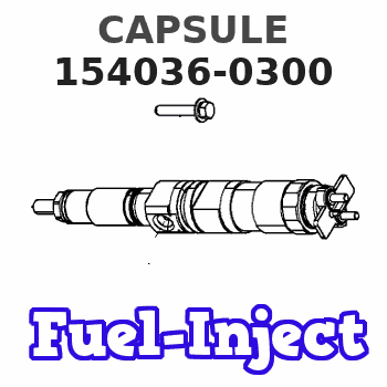
Information capsule
BOSCH
9 421 617 017
9421617017
ZEXEL
154036-0300
1540360300
ISUZU
5157290530
5157290530
Rating:
Include in ###:
Cross reference number
Zexel num
Bosch num
Firm num
Name
154036-0300
9 421 617 017
5157290530 ISUZU
CAPSULE
C 14GJ PLUG GOV
C 14GJ PLUG GOV
154036-0300
9 421 617 017
6053134760 HINO
CAPSULE
C 14GJ PLUG GOV
C 14GJ PLUG GOV
154036-0300
9 421 617 017
228112280A HINO
CAPSULE
A C 14GJ PLUG GOV
A C 14GJ PLUG GOV
154036-0300
9 421 617 017
S228112280A HINO
CAPSULE
B C 14GJ PLUG GOV
B C 14GJ PLUG GOV
154036-0300
9 421 617 017
ME704568 MITSUBISHI
CAPSULE
C 14GJ PLUG GOV
C 14GJ PLUG GOV
154036-0300
9 421 617 017
1938290001 NISSAN
CAPSULE
C 14GJ PLUG GOV
C 14GJ PLUG GOV
154036-0300
9 421 617 017
1938290001 NISSAN-DIESEL
CAPSULE
C 14GJ PLUG GOV
C 14GJ PLUG GOV
154036-0300
9 421 617 017
1312961280 ISHIKAWAJIMA-S
CAPSULE
C 14GJ PLUG GOV
C 14GJ PLUG GOV
154036-0300
9 421 617 017
EZ40060XX128 M.BISHI-HI.-NAG
CAPSULE
C 14GJ PLUG GOV
C 14GJ PLUG GOV
154036-0300
9 421 617 017
9421617017 BOSCH
CAPSULE
C 14GJ PLUG GOV
C 14GJ PLUG GOV
Information:
(1) Gear. If new gear is required, replace camshaft assembly. The heat treatment of the gear is damaged if heated.(2) Diameter of the surfaces (journals) for the camshaft bearings (new) ... 69.850 0.013 mm (2.7500 .0005 in) Bore in front bearing for the camshaft (after assembly) ... 69.969 0.048 mm (2.7547 .0019 in)Bore in the other six bearings for the camshaft (after assembly) ... 69.982 0.061 mm (2.7552 .0024 in)(3) Thickness of thrust plate (new) ... 4.65 0.03 mm (.183 .001 in) End play of the camshaft ... 0.10 to 0.26 mm (.004 to .010 in)(4) Camshaft. (5) Height of camshaft lobes.To find lobe height, use the procedure that follows:A. Measure camshaft lobe height (5).B. Measure base circle (7).C. Subtract base circle (STEP B) from lobe height (STEP A). The difference is actual lobe lift (6).D. Specified camshaft lobe lift (6) is: Camshaft Assemblya. Exhaust lobe ... 10.5 mm (.413 in)b. Inlet lobe ... 10.5 mm (.413 in)Maximum permissible difference between actual lobe lift (STEP C) and specified lobe lift (STEP D) is 0.13 mm (.005 in)Inlet Valve Timing
1. Check the No. 1 inlet valve lash with the engine stopped. The valve lash must be 0.30 to 0.46 mm (.012 to .018 in). If the valve lash is not in this range, adjust the lash to 0.38 mm (.015 in).2. Mark Top Center Position of the crankshaft on the vibration damper or pulley.3. Use a dial indicator to measure the inlet valve movement.4. Rotate the crankshaft in the direction of normal engine rotation. Stop when the inlet valve is 1.91 mm (.075 in) off its seat in the opening sequence.At this point the crankshaft Top Center Position Mark must be ... 5 2 degrees After Top CenterChecking Valve-Camshaft Timing (field procedure)
The following procedure will simplify the checking of the camshaft timing procedures.1. Set the No. 3 inlet bridge adjustment. Refer to SENR6547 (Testing And Adjusting).2. Set the No. 3 inlet valve lash. Refer to SENR6547 (Testing And Adjusting).3. Install the bolt in the flywheel with No. 1 piston at top center.4. Install the dial indicator (magnetic base) to No. 3 inlet bridge.5. Remove the bolt from the flywheel.6. Set the indicator at zero and rotate the engine in the normal direction of operation (counterclockwise as viewed from the flywheel end) until dial travel stops.The correct setting should be ... 14.21 0.25 mm (.560 .010 in)
Have questions with 154036-0300?
Group cross 154036-0300 ZEXEL
Isuzu
154036-0300
9 421 617 017
5157290530
CAPSULE
Hino
154036-0300
9 421 617 017
6053134760
CAPSULE
154036-0300
9 421 617 017
228112280A
CAPSULE
154036-0300
9 421 617 017
S228112280A
CAPSULE
Mitsubishi
154036-0300
9 421 617 017
ME704568
CAPSULE
Nissan
154036-0300
9 421 617 017
1938290001
CAPSULE
Nissan-Diesel
154036-0300
9 421 617 017
1938290001
CAPSULE
Ishikawajima-S
154036-0300
9 421 617 017
1312961280
CAPSULE
M.Bishi-Hi.-Nag
154036-0300
9 421 617 017
EZ40060XX128
CAPSULE
Bosch
154036-0300
9 421 617 017
9421617017
CAPSULE