Information bushing
BOSCH
9 421 612 626
9421612626
ZEXEL
154206-5200
1542065200
ISUZU
8972879980
8972879980
Rating:
Include in ###:
Cross reference number
Zexel num
Bosch num
Firm num
Name
154206-5200
9 421 612 626
8972879980 ISUZU
BUSHING
C 14GJ COLLAR GOV
C 14GJ COLLAR GOV
154206-5200
9 421 612 626
223321910A HINO
BUSHING
C 14GJ COLLAR GOV
C 14GJ COLLAR GOV
154206-5200
9 421 612 626
1930199102 NISSAN-DIESEL
BUSHING
C 14GJ COLLAR GOV
C 14GJ COLLAR GOV
Information:
The fuel system is a pressure type with a separate injection pump and injection valve for each cylinder. Fuel is injected into a precombustion chamber, not directly into the cylinder.A transfer pump supplies fuel filtered through primary (optional) and final filters to a manifold in the injection pump housing.The transfer pump supplies more fuel than is required for injection, so a bypass valve is built into the pressure side of the pump. The valve limits the maximum pressure within the supply system.An air vent valve located on the fuel filter base permits the removal of air in the injection pump supply system after servicing the filter or whenever air is allowed to enter the system. Air is removed by opening the valve and pressurizing the fuel system. The priming pump. The vent valve must be open and the pump operated until a stream of fuel, without air bubbles, flows from the vent line. Fuel Injection Pump Operation
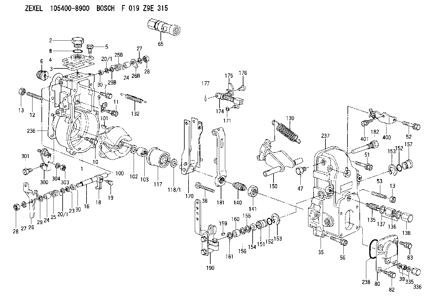
Fuel enters the fuel injection pump housing from the fuel filter through the fuel manifold and enters the fuel injection pump through the inlet port. The injection pump plungers and lifters are lifted by the cam lobes on the fuel system's own camshaft and always make a full stroke. The lifters are held against the cam lobes by springs. Each pump measures the amount of fuel to be injected into its respective cylinder and delivers it to the fuel injection nozzle.The amount of fuel pumped per stroke is varied by turning the plunger in the barrel. The plunger is turned by the governor action through the gear segmented sliding rack which turns the gear segment on the bottom of the pump plunger. The position of the scroll on the plunger determines the amount of fuel injected into the cylinders. Fuel Pump
Figures A, B and C illustrate the functioning of an injection pump as the plunger makes a stroke.In Fig. A the plunger is down and the inlet port is uncovered. Fuel flows into the space above the plunger through the slot and into the recess around the plunger.In Fig. B the plunger has started up and the port is covered. The fuel is trapped and will be forced through a check valve, fuel line, and injection valve.In Fig. C the plunger has risen until the port is uncovered by the recess in the plunger. The fuel can now escape back through the port into the fuel manifold and injection will cease.Note that the recess in the pump plunger forms a helix around the upper end of the plunger. Figures D, E and F illustrate how rotating the pump plunger affects the quantity of fuel injected.In Fig. D the plunger has been rotated into the shut-off position. The slot connecting the top of the plunger with the recess is in line with the port; therefore, no fuel can be trapped and injected.In Fig. E the plunger has been rotated into the idling position. The narrow part of the plunger formed by the helix
Have questions with 154206-5200?
Group cross 154206-5200 ZEXEL
Isuzu
154206-5200
9 421 612 626
8972879980
BUSHING
Hino
154206-5200
9 421 612 626
223321910A
BUSHING
Nissan-Diesel
154206-5200
9 421 612 626
1930199102
BUSHING