Information bracket
BOSCH
9 461 611 511
9461611511
ZEXEL
146626-5220
1466265220
NISSAN
16711W3411
16711w3411
Rating:
Include in ###:
Cross reference number
Zexel num
Bosch num
Firm num
Name
146626-5220
9 461 611 511
16711W3411 NISSAN
BRACKET
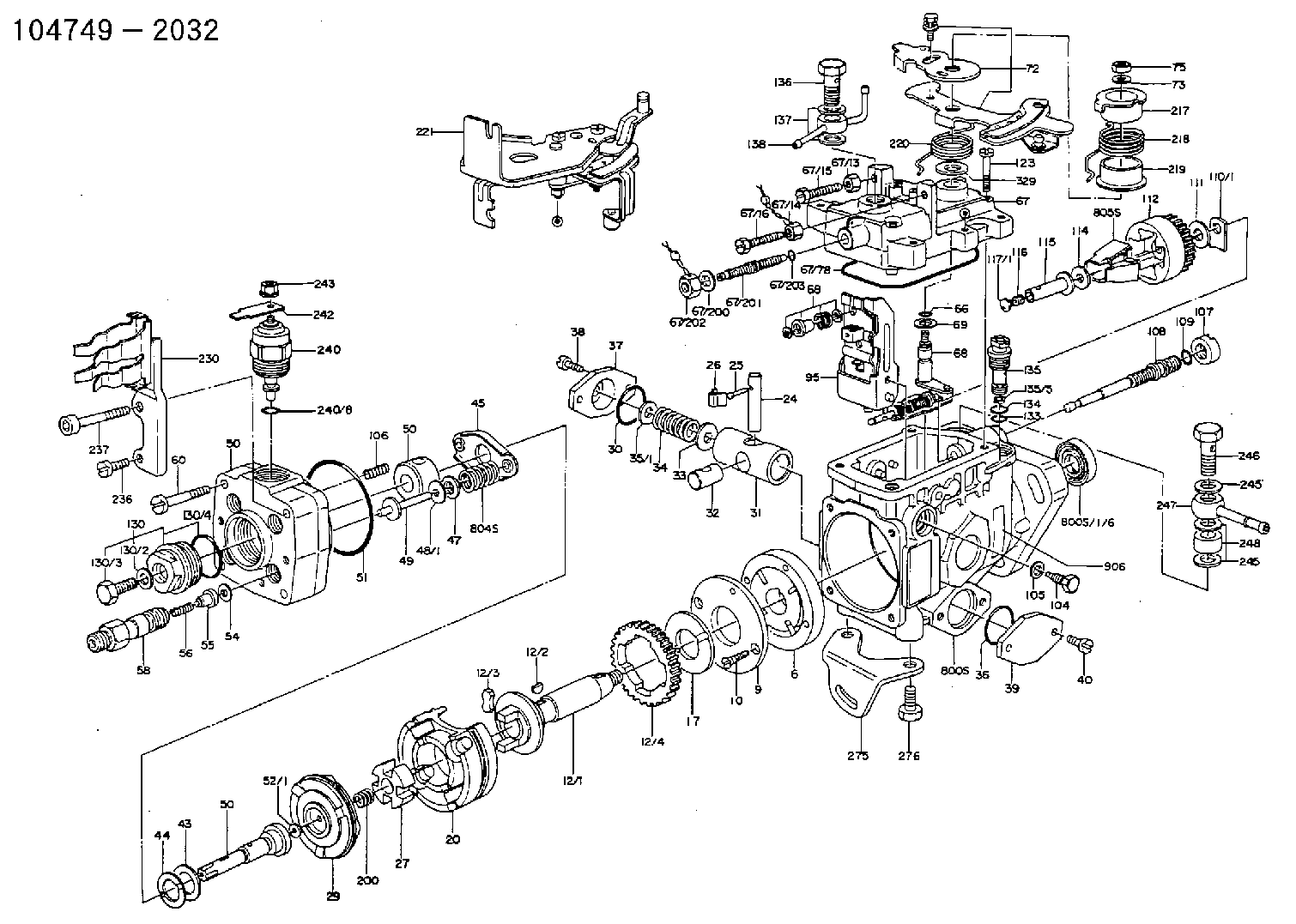
C 11FV BRACKET parts(VE) Others
C 11FV BRACKET parts(VE) Others
Information:
Test Procedure
System Operation
The discrete output modules are digital modules. The output modules provide control of voltage. An output module provides power for the following list of functions: Energizing the Lamps, Energizing the Relays, Energizing the Fuel Shutoff Solenoid and Energizing the Air Shutoff Solenoid.
Illustration 1 g00563503
Diagram of the programmable logic controller
Illustration 2 g00563596
Schematic of the discrete outputFunctional Test
Check the electrical connectors and check the wiring.
Bodily contact with electrical potential can cause bodily injury or death.To avoid the possibility of injury or death, ensure that the main power supply has been disconnected before performing any maintenance or removing any modules.
Disconnect the power supply.
Check the electrical connectors and check the wiring for damage or bad connections.
Verify that all modules are properly seated.
Verify the status of the LED on the SLC 5/04.The results of the preceding procedure are in the following list:
All of the components are fully installed. All of the components are free of corrosion. All of the components are free of damage. All of the modules are properly seated. Proceed to 2.
The components are not fully installed. The components are not free of corrosion. The components are damaged. All of the modules are not properly seated. Repair the component. Verify that the repair resolves the problem. STOP.
Test the channel.
Disconnect the load from the channel that is being tested.
Create the condition that activates the channel.The results of the preceding procedure are in the following list:
The LED on the module illuminates. Proceed to 3.
The LED on the module does not illuminate. Replace the module. Verify that the repair resolves the problem. Refer to Maintenance Procedure, "Input Module and Output Module - Replace". Stop.
Measure the voltage of the channel.
Measure the voltage of the channel.The results of the preceding procedure are in the following list:
The voltage of the channel and the voltage of the module are equal. Stop.
The voltage of the channel and the voltage of the module are not equal. Refer to Troubleshooting, "System Power"Stop.
Have questions with 146626-5220?
Group cross 146626-5220 ZEXEL
Nissan
146626-5220
9 461 611 511
16711W3411
BRACKET