Information bleeder screw
BOSCH
9 423 617 064
9423617064
ZEXEL
156633-8400
1566338400
ISUZU
1157890790
1157890790
Rating:
Include in ###:
Cross reference number
Zexel num
Bosch num
Firm num
Name
156633-8400
9 423 617 064
1157890790 ISUZU
BLEEDER SCREW
C 14GU BOLT COUP
C 14GU BOLT COUP
156633-8400
9 423 617 064
228113870A HINO
BLEEDER SCREW
C 14GU BOLT COUP
C 14GU BOLT COUP
156633-8400
9 423 617 064
S228113870A HINO
BLEEDER SCREW
A C 14GU BOLT COUP
A C 14GU BOLT COUP
156633-8400
9 423 617 064
1682799109 NISSAN-DIESEL
BLEEDER SCREW
C 14GU BOLT COUP
C 14GU BOLT COUP
Information:
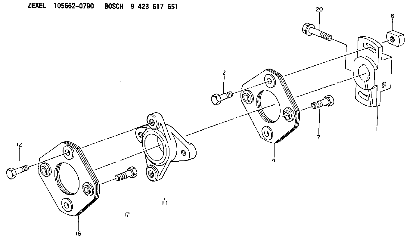
start by:a) remove turbocharger 1. Put the turbocharger in position on tool (A). Move tool (A) so the compressor housing is up. 2. For installation alignment purposes, make a mark on the center housing and turbine housing. Bend down the lock plates and remove six bolts (1). If some of the bolts are hard to remove, put penetrating oil on the bolt and hit the flat of the bolt head with a punch and hammer. 3. Lift the center housing and turbine wheel out of the turbine housing. If the assembly is hard to get apart, lift up on the compressor housing and hit the turbine housing with a soft hammer. 4. Remove clamp (2) from the compressor housing. For installation alignment purposes, make a mark on the center housing and the compressor housing. 5. Lift the center housing out of the compressor housing. Put the turbine wheel in tooling (B).6. Remove nut (3) with a universal socket. Remove O-ring (4).
Do not put a side force on the shaft when the nut is removed.
7. Heat the compressor wheel in oil for no more than ten minutes. The temperature of the oil must be 350° 25°F (176° 14°C).
The bearing heating oil used to heat the compressor wheel must have a flash point above 400°F (204°C).
8. Immediately after removing the compressor wheel from the oil, put the center housing in a press and use tooling (C) and (D) to remove the compressor wheel and center housing from the shaft.
Do not let the turbine wheel hit the bottom of the press.
9. Put the turbine wheel in tooling (B) and remove ring (6) and shroud (5). 10. Remove three bolts (7) and the three lock plates from center housing (8). 11. Remove plate (9) with tool (E). Remove the O-ring from plate (9). 12. Remove spacer (10) from plate (9). Remove collar (11) and thrust bearing (15). Remove bearing (12) and put a long dye mark on the top face of the bearing. Use tool (F) to remove rings (16) and (13). Remove bearing (17) and put a short dye mark on the top face of the bearing. Remove ring (14) with tool (F). The dye marks are for identification when installing the bearings.13. Inspect all parts and install new parts if needed. Use Special Instruction Form No. GMG00153-01, Turbocharger Reconditioning, Form No. FEG45138, Analyzing Turbocharger Failure and Video Tape JEG08054 (1/2 inch reel) (JEG09052-cassette), Turbocharger Reconditioning I (AIRESEARCH) for references.Assemble Turbocharger
1. Make sure all oil passages are open and clean. Put clean engine oil on all parts before assembly. 2. Install ring (3) with tool (A). Install bearing (4) with the short dye mark up. Install rings (2) and (1) with tool (A). Rings (1), (2) and (3) must be installed with the round edge toward the bearing. 3. Install shroud (5) on the turbine shaft. Install ring (6). Put 6V2055 High Vacuum Grease on ring (6) and fill the groove for the ring to one half depth all
Have questions with 156633-8400?
Group cross 156633-8400 ZEXEL
Isuzu
156633-8400
9 423 617 064
1157890790
BLEEDER SCREW
Hino
156633-8400
9 423 617 064
228113870A
BLEEDER SCREW
156633-8400
9 423 617 064
S228113870A
BLEEDER SCREW
Nissan-Diesel
156633-8400
9 423 617 064
1682799109
BLEEDER SCREW