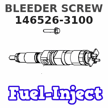
Information bleeder screw
BOSCH
9 461 618 128
9461618128
ZEXEL
146526-3100
1465263100
ISUZU
8944085150
8944085150
Rating:
Include in ###:
Cross reference number
Zexel num
Bosch num
Firm num
Name
146526-3100
9 461 618 128
8944085150 ISUZU
BLEEDER SCREW
C 11FV BOLT parts(VE) Others
C 11FV BOLT parts(VE) Others
146526-3100
9 461 618 128
SE4224183 MAZDA
BLEEDER SCREW
C 11FV BOLT parts(VE) Others
C 11FV BOLT parts(VE) Others
146526-3100
9 461 618 128
V11624183 MAZDA
BLEEDER SCREW
A C 11FV BOLT parts(VE) Others
A C 11FV BOLT parts(VE) Others
Information:
7. Remove inner fuel lines (13). 8. Remove Jacobs washers (14) and Jacobs shims (15) from the Jacobs stud assemblies. 9. Remove bolt (17) and two Jacobs stud assemblies (16) that hold the rocker shaft assembly to the head. Remove rocker shaft assembly (18). 10. Remove Jacobs exhaust valve bridges (20) from the exhaust valves only. The intake valves have the Caterpillar intake valve bridges. Remove the Caterpillar intake valve bridges (19).Install Jacobs Engine Brake
Do each step for each end of the engine. The front half is shown.1. Put clean engine oil on the bridges and dowels.2. Install Jacobs exhaust valve bridges (20) and the Caterpillar intake valve bridges (19) on the dowels.3. Keep hand pressure on the bridges, and turn the adjustment screw clockwise until contact is made with the valve stem. Turn the screw an extra 20° to 30°. This will make the dowel straight in the guide and compensate for gap (slack) in the threads. Hold the adjustment screw in this position, and tighten the locknut to a torque of 28 4 N m (21 3 lb.ft.). 4. Put rocker shaft assembly (18) in position on the cylinder head. 5. Install Jacobs washers (21) on the Jacobs stud assemblies (16). Put clean oil on the threads, and install washer and bolt (17) and Jacobs stud assemblies (16). Tighten the center bolt and Jacobs stud assemblies in increments of 70 N m (50 lb.ft.) each until a final torque of 450 N m (330 lb.ft.) is obtained.6. Make an adjustment to the valves to have a clearance of .015 (0.38 mm) for the intake valves and .030 (0.76 mm) for the exhaust valves. Tighten the locknuts to a torque of 28 4 N m (21 3 lb.ft.), and check the valve clearance again. See Testing And Adjusting for the correct procedure. 7. Install a new Jacobs O-ring seal (22) on the Jacobs oil supply adapter in the rocker shaft assembly. Put clean oil on the Jacobs O-ring seal.
Do not cause damage to the O-ring seals on the inner fuel lines.
8. Install inner fuel lines (13). Tighten the fuel line nuts to a torque of 40 7 N m (30 5 lb.ft.) with tooling (A) and (B). The Jacobs brake for the 3406B Truck Engine has only one support bracket (11).9. Put jacobs support brackets (11) in position as shown. Put oil on the threads of Jacobs bolts (12). Install the washers on the Jacobs bolts. Install Jacobs bolts (12) that hold the Jacobs support bracket in place. Tighten the Jacobs bolts to a torque of 450 N m (330 lb.ft.). 10. Install Jacobs washers (14) on the Jacobs stud assemblies.
Be extra careful not to cause damage to the Jacobs oil supply adapter O-ring seal when the Jacobs brake housing assembly is installed.
The brake housing assembly with the mark "FRONT" on it must be installed on the front three cylinders. The brake housing assembly with the mark "REAR" must be installed
Have questions with 146526-3100?
Group cross 146526-3100 ZEXEL
Isuzu
146526-3100
9 461 618 128
8944085150
BLEEDER SCREW
Mazda
146526-3100
9 461 618 128
SE4224183
BLEEDER SCREW
146526-3100
9 461 618 128
V11624183
BLEEDER SCREW