Information bleeder screw
BOSCH
9 411 610 581
9411610581
ZEXEL
139006-3800
1390063800
ISUZU
1157298010
1157298010

Rating:
Include in ###:
Number on scheme 173/1

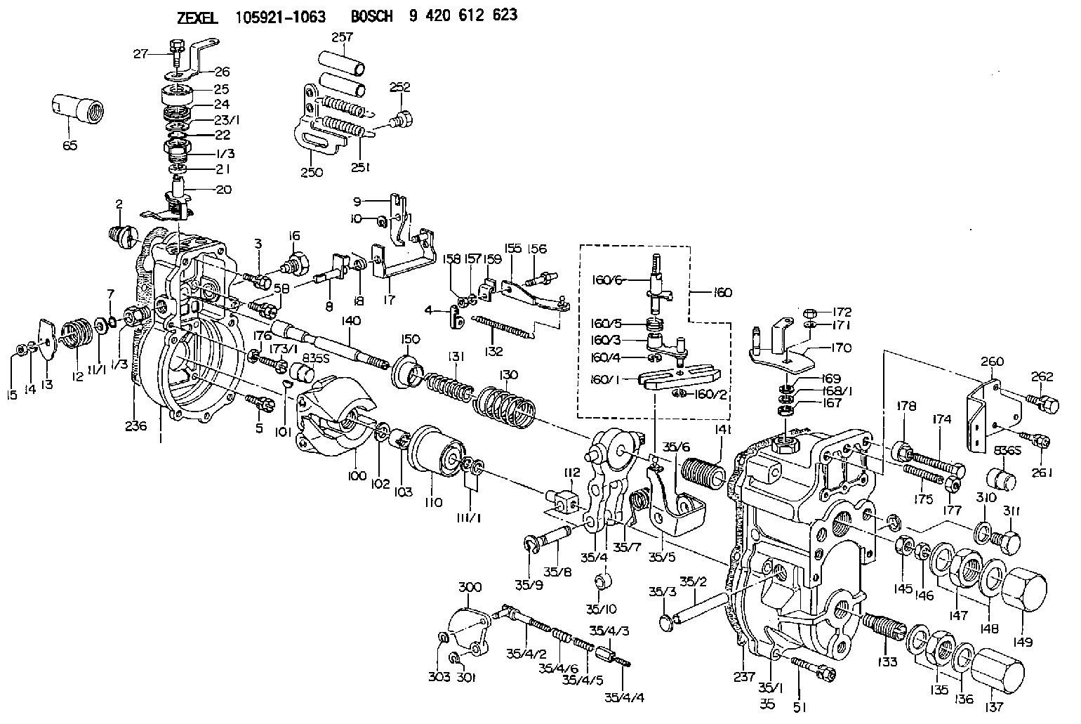
1059211063
as BLEEDER SCREW
M6P1.0L35
1059211870
as BLEEDER SCREW
1059211871
as BLEEDER SCREW
M6P1.0L35
Cross reference number
Zexel num
Bosch num
Firm num
Name
139006-3800
9 411 610 581
1157298010 ISUZU
BLEEDER SCREW
C 90HY BOLT Standard parts Others
C 90HY BOLT Standard parts Others
139006-3800
9 411 610 581
228114390A HINO
BLEEDER SCREW
C 90HY BOLT Standard parts Others
C 90HY BOLT Standard parts Others
139006-3800
9 411 610 581
ME716789 MITSUBISHI
BLEEDER SCREW
C 90HY BOLT Standard parts Others
C 90HY BOLT Standard parts Others
139006-3800
9 411 610 581
1925989TA4 NISSAN
BLEEDER SCREW
C 90HY BOLT Standard parts Others
C 90HY BOLT Standard parts Others
139006-3800
9 411 610 581
19382Z9104 NISSAN-DIESEL
BLEEDER SCREW
C 90HY BOLT Standard parts Others
C 90HY BOLT Standard parts Others
Information:
Start By:a. remove rocker arm assemblies and push rods1. Disconnect the governor control linkage. See the 3114 & 3116 Engines Governor Service Manual, Form No. SENR6454.
Do not move the fuel control linkage or the injector racks with out the Injector Compressors [Tool (A)] installed. Damage to the fuel injectors can result. After installation of Tool (A), tap on the top of each fuel injector lightly with a rubber mallet to prevent any binding or side loading in the fuel injectors.
2. When removing the fuel control linkage with the fuel injectors in place, install Tool (A) on the fuel injectors, and slightly compress the injector springs.3. Remove four bolts (1) and fuel control linkage (2). The following steps are for the installation of the fuel control linkage.4. Be sure the two screws in each inboard bracket are loose.5. Put fuel control linkage in position on the cylinder head assembly. Be sure all injector racks are engaged and the small dowel in each mounting bracket is in the proper position before tightening bolts (1). Install four bolts (1), and tighten them as follows: a. Tighten the two outer bearing bracket mounting bolts.b. Tighten the inner bearing bracket(s) mounting bolt(s).c. Position the inner bearing(s) to allow free rotation of the rack control rod.d. Tighten the two screws in on each inner bracket(s) to a torque of 3.5 0.2 N m (31 2 lb in).e. The control rod must rotate when a force of 4.4 N (1 lb) or less is applied to control lever (3) in the direction indicated by arrows.6. Connect the governor control linkage. See the 3114 & 3116 Engines Governor Service Manual, Form No. SENR6454.7. After installation of the rocker arm assemblies and push rods, Check and/or adjust the following: Injector Synchronization, Fuel Setting, Fuel Timing, Valve Lash. See the 3114 & 3116 Diesel Truck Engines Systems Operation Testing & Adjusting module, Form No. SENR6437 to check and/or adjust the above items.End By:a. install rocker arm assemblies and push rods
Have questions with 139006-3800?
Group cross 139006-3800 ZEXEL
Isuzu
139006-3800
9 411 610 581
1157298010
BLEEDER SCREW
Hino
139006-3800
9 411 610 581
228114390A
BLEEDER SCREW
Mitsubishi
139006-3800
9 411 610 581
ME716789
BLEEDER SCREW
Nissan
139006-3800
9 411 610 581
1925989TA4
BLEEDER SCREW
Nissan-Diesel
139006-3800
9 411 610 581
19382Z9104
BLEEDER SCREW