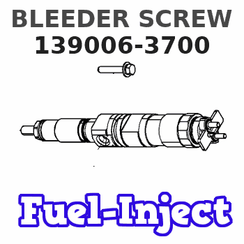
Information bleeder screw
BOSCH
9 411 610 580
9411610580
ZEXEL
139006-3700
1390063700
ISUZU
1157298000
1157298000
Rating:
Include in ###:
Number on scheme 173/1

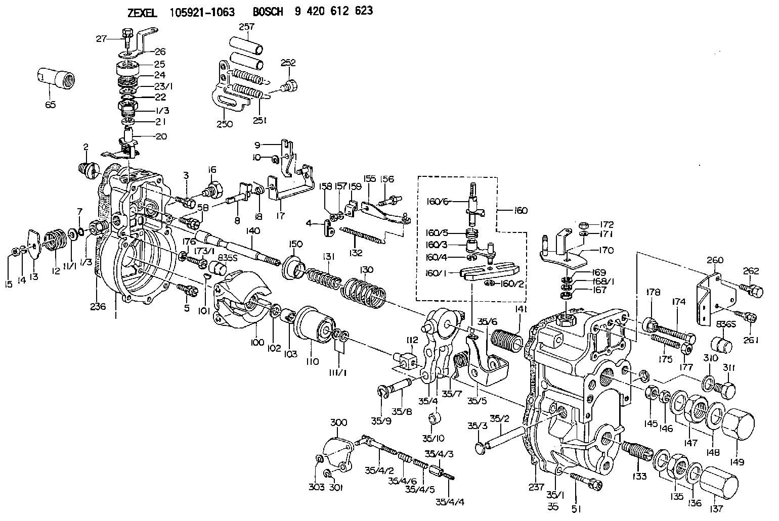
1059211063
as BLEEDER SCREW
M6P1.0L34
1059211870
as BLEEDER SCREW
1059211871
as BLEEDER SCREW
M6P1.0L34
Cross reference number
Zexel num
Bosch num
Firm num
Name
139006-3700
9 411 610 580
1157298000 ISUZU
BLEEDER SCREW
C 90HY BOLT Standard parts Others
C 90HY BOLT Standard parts Others
139006-3700
9 411 610 580
228114380A HINO
BLEEDER SCREW
C 90HY BOLT Standard parts Others
C 90HY BOLT Standard parts Others
139006-3700
9 411 610 580
ME716788 MITSUBISHI
BLEEDER SCREW
C 90HY BOLT Standard parts Others
C 90HY BOLT Standard parts Others
139006-3700
9 411 610 580
1925989TA3 NISSAN
BLEEDER SCREW
C 90HY BOLT Standard parts Others
C 90HY BOLT Standard parts Others
139006-3700
9 411 610 580
19382Z9103 NISSAN-DIESEL
BLEEDER SCREW
C 90HY BOLT Standard parts Others
C 90HY BOLT Standard parts Others
Information:
Start By:a. remove rocker arm assemblies and push rods 1. Remove injector hold down bolt (1).
Do not pry on the injector hold down bracket. Damage to the injector could occur. The injector has a notch in it on the side opposite the rack. This notch is used for prying the injector loose. Also, do not move the fuel injector rack without the injector spring slightly compressed. Damage to the injector could occur.
2. Use Tool (A) to loosen the fuel injector; then rotate the fuel injector to disengage the injector rack from the fuel control linkage. Remove the fuel injector. Be sure both O-ring seals (2) are on the fuel injector. The following steps are for the installation of the unit fuel injectors.3. Check the condition of O-ring seals (2). If the seals are damaged, use new parts for replacement. Install the O-ring seals on in the fuel injector.4. Lubricate the O-ring seals on the fuel injector with clean engine oil.5. Position the fuel injector in the cylinder head assembly; then rotate it to engage the injector rack with the fuel control linkage. Push down on the top of the fuel injector so the O-ring seals slide into the bore in the cylinder head assembly. Be sure the fuel injector is seated properly before installing bolt (1) that holds it in position. Do not use bolt (1) to pull the fuel injector down into the cylinder head assembly.6. Install bolt (1), and tighten it.7. After installation of the rocker arm assemblies and push rods, Check and/or adjust the following: Injector Synchronization, Fuel Setting, Fuel Timing, Valve Lash. See the 3114 & 3116 Diesel Truck Engines Systems Operation Testing & Adjusting module, Form No. SENR6437 to check and/or adjust the above items.End By:a. install rocker arm assemblies and push rods
Have questions with 139006-3700?
Group cross 139006-3700 ZEXEL
Isuzu
139006-3700
9 411 610 580
1157298000
BLEEDER SCREW
Hino
139006-3700
9 411 610 580
228114380A
BLEEDER SCREW
Mitsubishi
139006-3700
9 411 610 580
ME716788
BLEEDER SCREW
Nissan
139006-3700
9 411 610 580
1925989TA3
BLEEDER SCREW
Nissan-Diesel
139006-3700
9 411 610 580
19382Z9103
BLEEDER SCREW