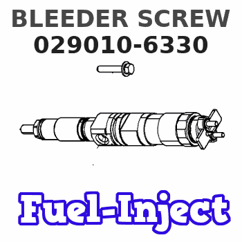
Information bleeder screw
BOSCH
9 442 611 336
9442611336
ZEXEL
029010-6330
0290106330
ISUZU
9813453350
9813453350
Rating:
Include in #1:
108622-1185
as _
Include in ###:
Number on scheme 251

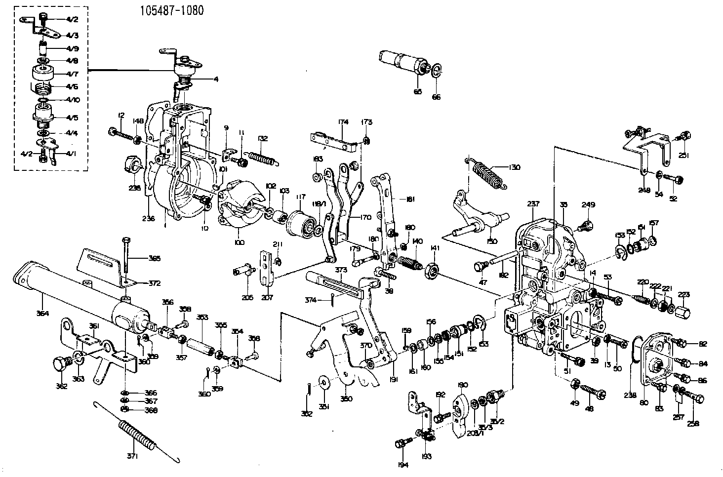
1054871080
as BLEEDER SCREW
M6P1.0L13
1054888640
as BLEEDER SCREW
1054891950
as BLEEDER SCREW
M6P1.0L13
Cross reference number
Zexel num
Bosch num
Firm num
Name
029010-6330
9 442 611 336
9813453350 ISUZU
BLEEDER SCREW
D 90HY BOLT Standard parts Others
D 90HY BOLT Standard parts Others
029010-6330
9 442 611 336
6073131270 HINO
BLEEDER SCREW
D 90HY BOLT Standard parts Others
D 90HY BOLT Standard parts Others
029010-6330
9 442 611 336
228112860A HINO
BLEEDER SCREW
A D 90HY BOLT Standard parts Others
A D 90HY BOLT Standard parts Others
029010-6330
9 442 611 336
ME705293 MITSUBISHI
BLEEDER SCREW
D 90HY BOLT Standard parts Others
D 90HY BOLT Standard parts Others
029010-6330
9 442 611 336
1937990001 NISSAN
BLEEDER SCREW
D 90HY BOLT Standard parts Others
D 90HY BOLT Standard parts Others
029010-6330
9 442 611 336
1937990001 NISSAN-DIESEL
BLEEDER SCREW
D 90HY BOLT Standard parts Others
D 90HY BOLT Standard parts Others
029010-6330
9 442 611 336
E266402370Z DAIHATSU
BLEEDER SCREW
D 90HY BOLT Standard parts Others
D 90HY BOLT Standard parts Others
029010-6330
9 442 611 336
C30301022T KOBE--ENGIN.
BLEEDER SCREW
D 90HY BOLT Standard parts Others
D 90HY BOLT Standard parts Others
Information:
1. Remove two bolts (4) that hold tube assembly (1) to the engine block.2. Remove one bolt (not shown) that holds pipe (3) to oil pump (2). Remove the pipe and tube assembly as a unit. 3. Remove three bolts (5). Remove oil pump (2).Install Oil Pump
1. Check the O-ring seals for damage. If damaged, use new parts for replacement. 2. Put oil pump (1) in position. Install the three bolts that hold the oil pump to the engine. 3. Put clean engine oil on all O-ring seals, and install pipe (2) and tube assembly (3) in the oil pump as a unit. Install two bolts that fasten the pipe assembly to the engine block.End By:a. install oil panDisassemble Oil Pump
Start By:a. remove oil pump1. Remove the bolt and washer that hold the gear on the shaft. 2. Use Tooling (A) to remove drive gear (1) from the shaft. Remove the key from shaft. 3. Remove retainer (3) for the bypass valve.4. Remove the spring and bypass valve.5. Remove cover (2) from the pump body. 6. Use Tooling (B) to remove the bearings from the cover. 7. Remove gears (5) from pump body (4).8. Use Tooling (B) to remove the bearings from the pump body.Assemble Oil Pump
1. Use Tooling (A) to install the bearings in the main pump body until they are even with the outside surface of the pump body. Install the bearings so the junctions in the bearings are 30 15 degrees from the center of the bearing bores and toward the oil pump outlet passage (2) as shown. 2. Install idler gear (1) and drive gear (3) in the oil pump body. Put clean engine oil on the bearings and gears. 3. Use Tooling (A) to install the bearings in cover (4) until they are even with the outside surface of the cover. Install the bearings so the junctions in the bearings are 30 15 degrees from the center of the bearing bores and toward the oil pump outlet passage as shown. 4. Install bypass valve (5), spring (6), spacer and the retainer in the pump body.5. Install the key on the shaft. 6. Install gear (7) on the shaft. Install the washer and bolt that holds the gear on the shaft. Tighten the bolt to a torque of 55 7 N m (41 5 lb ft).7. Make sure the pump turns freely by hand after it is assembled.End By:a. install oil pump
Have questions with 029010-6330?
Group cross 029010-6330 ZEXEL
Isuzu
029010-6330
9 442 611 336
9813453350
BLEEDER SCREW
Hino
029010-6330
9 442 611 336
6073131270
BLEEDER SCREW
029010-6330
9 442 611 336
228112860A
BLEEDER SCREW
Mitsubishi
029010-6330
9 442 611 336
ME705293
BLEEDER SCREW
Nissan
029010-6330
9 442 611 336
1937990001
BLEEDER SCREW
Nissan-Diesel
029010-6330
9 442 611 336
1937990001
BLEEDER SCREW
Daihatsu
029010-6330
9 442 611 336
E266402370Z
BLEEDER SCREW
Kobe--Engin.
029010-6330
9 442 611 336
C30301022T
BLEEDER SCREW