Information autom. advance mechanism
BOSCH
9 420 615 726
9420615726
ZEXEL
105687-0310
1056870310
ISUZU
1157403400
1157403400
Rating:
Scheme ###:
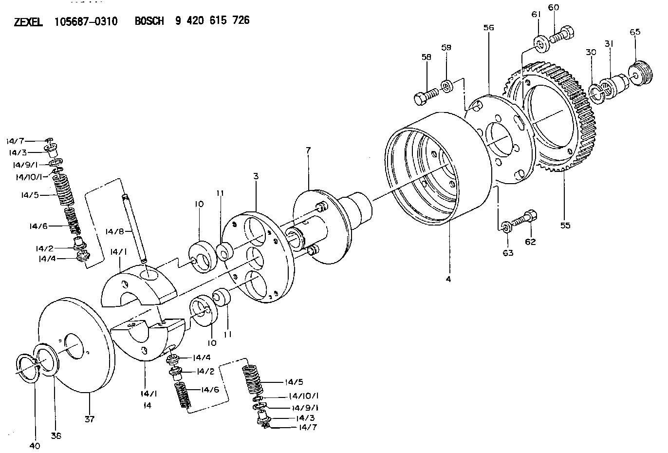
| 3. | [1] | 156873-0100 | PLATE |
| 4. | [1] | 156870-0000 | TIMING-DEVICE HOUSING |
| 7. | [1] | 156871-0520 | FLANGE BUSHING |
| 10. | [2] | 156723-0300 | ECCENTRIC DISC |
| 10. | [2] | 156723-0300 | ECCENTRIC DISC |
| 11. | [2] | 156723-0400 | ECCENTRIC DISC |
| 11. | [2] | 156723-0400 | ECCENTRIC DISC |
| 14. | [1] | 156880-3420 | FLYWEIGHT ASSEMBLY |
| 14/1. | [2] | 156872-0520 | FLYWEIGHT |
| 14/1. | [2] | 156872-0520 | FLYWEIGHT |
| 14/2. | [4] | 156877-0700 | SLOTTED WASHER |
| 14/2. | [4] | 156877-0700 | SLOTTED WASHER |
| 14/3. | [4] | 156877-0800 | SLOTTED WASHER |
| 14/3. | [4] | 156877-0800 | SLOTTED WASHER |
| 14/4. | [4] | 156727-0000 | SLOTTED WASHER |
| 14/4. | [4] | 156727-0000 | SLOTTED WASHER |
| 14/5. | [4] | 156885-0200 | COMPRESSION SPRING |
| 14/5. | [4] | 156885-0200 | COMPRESSION SPRING |
| 14/6. | [4] | 156884-8000 | COMPRESSION SPRING |
| 14/6. | [4] | 156884-8000 | COMPRESSION SPRING |
| 14/7. | [4] | 156729-0500 | LOCKING WASHER |
| 14/7. | [4] | 156729-0500 | LOCKING WASHER |
| 14/8. | [2] | 156876-0500 | PIN |
| 14/9/1. | [0] | 156808-1000 | SHIM D19&16.3T0.1 |
| 14/9/1. | [0] | 156808-1100 | SHIM D19&16.3T0.3 |
| 14/9/1. | [0] | 156808-1100 | SHIM D19&16.3T0.3 |
| 14/9/1. | [0] | 156808-1200 | SHIM D19&16.3T0.5 |
| 14/9/1. | [0] | 156808-1300 | SHIM D19&16.3T1.0 |
| 14/10/1. | [0] | 156728-0800 | SHIM D19&15T0.1 |
| 14/10/1. | [0] | 156728-0900 | SHIM D19&15T0.3 |
| 14/10/1. | [0] | 156728-1000 | SHIM D19&15T0.5 |
| 14/10/1. | [0] | 156728-1100 | SHIM D19&15T1.0 |
| 14/10/1. | [0] | 156728-2000 | SHIM D19&15T0.4 |
| 14/10/1. | [0] | 156728-2000 | SHIM D19&15T0.4 |
| 14/10/1. | [0] | 156728-2100 | SHIM D19&15T0.7 |
| 30. | [1] | 156809-0000 | LOCKING WASHER |
| 31. | [1] | 156809-0100 | UNION NUT |
| 37. | [1] | 156879-0901 | COVER |
| 38. | [1] | 156879-0700 | SHIM |
| 40. | [1] | 016020-3840 | LOCKING WASHER |
| 55. | [1] | 156878-0100 | TOOTHED GEAR |
| 56. | [1] | 156879-1300 | FLANGE;TIMING DEVICE |
| 58. | [4] | 156879-0000 | BLEEDER SCREW |
| 59. | [4] | 156879-1400 | PLAIN WASHER |
| 60. | [4] | 156879-0200 | BLEEDER SCREW |
| 61. | [4] | 156879-0500 | PLAIN WASHER |
| 62. | [4] | 156633-4100 | BLEEDER SCREW |
| 63. | [4] | 156879-0300 | PLAIN WASHER |
| 65. | [1] | 156879-0600 | CAP |
Cross reference number
Zexel num
Bosch num
Firm num
Name
Information:
GENERAL
1. Schematic
Schematic2. Specifications INSPECTION
1. Oil pumpVisually check the pump for rough rotation or other defects. Replace the pump assembly if defective.
Checking oil pump2. Oil pressure switch (1) Test for continuity between the terminal and body with an ohmmeter as shown in the illustration. No continuity is the cause for replacing the switch.
Testing oil pressure switch (1)(2) Insert a small diameter bar into the oil hole in the switch and lightly push it in to test for no continuity as shown in the illustration. Any continuity is the cause for replacing the switch.(3) Apply a pressure air of 0.5 kgf/cm2 (7 psi) [49 kPa] to the switch through the oil hole to test for no continuity. Any continuity is the cause for replacing the switch. Also, check for air leaks. Any air leak is an indication of a ruptured diaphragm. In such a case, replace the switch.
Testing oil pressure switch (2)3. Pressure relief valve (1) Check the valve seat for contact. Check the spring for damage.(2) Measure the oil pressure at which the relief valve opens (the oil pressure with the engine running at the rated rpm). If the pressure is not correct, remove the cap nut and increase or decrease the amount of shims. The engine oil pressure tap is located on the right side of the engine.
Checking pressure relief valve