Information autom. advance mechanism
ZEXEL
105681-5010
1056815010
HINO
225001820A
225001820a

Rating:
Scheme ###:
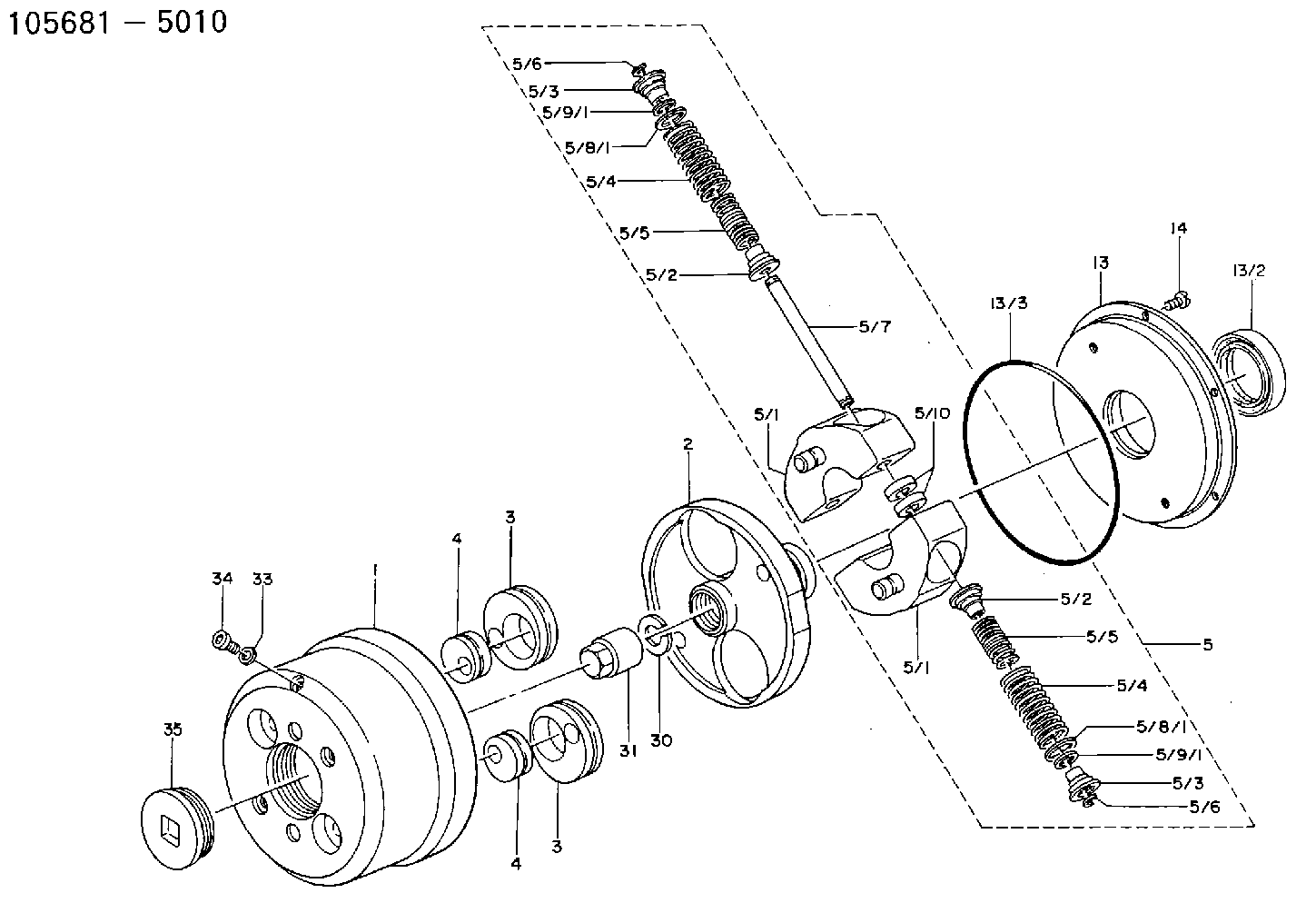
| 1. | [1] | 156800-0820 | TIMING-DEVICE HOUSING |
| 2. | [1] | 156801-5001 | FLANGE BUSHING |
| 3. | [2] | 156723-0300 | ECCENTRIC DISC |
| 3. | [2] | 156723-0300 | ECCENTRIC DISC |
| 4. | [2] | 156723-0400 | ECCENTRIC DISC |
| 4. | [2] | 156723-0400 | ECCENTRIC DISC |
| 5. | [1] | 156810-0220 | FLYWEIGHT ASSEMBLY |
| 5/1. | [2] | 156802-0820 | FLYWEIGHT |
| 5/1. | [2] | 156802-0820 | FLYWEIGHT |
| 5/2. | [4] | 156877-0400 | SLOTTED WASHER |
| 5/2. | [4] | 156877-0400 | SLOTTED WASHER |
| 5/3. | [4] | 156877-0300 | SLOTTED WASHER |
| 5/3. | [4] | 156877-0300 | SLOTTED WASHER |
| 5/4. | [4] | 156804-5000 | COMPRESSION SPRING |
| 5/4. | [4] | 156804-5000 | COMPRESSION SPRING |
| 5/5. | [4] | 156804-4901 | COMPRESSION SPRING |
| 5/5. | [4] | 156804-4901 | COMPRESSION SPRING |
| 5/6. | [4] | 156809-0300 | LOCKING WASHER |
| 5/6. | [4] | 156809-0300 | LOCKING WASHER |
| 5/7. | [2] | 156806-0000 | PIN |
| 5/8. | [4] | 156728-0020 | SHIM |
| 5/8/1. | [1] | 156728-0000 | SHIM |
| 5/8/1. | [1] | 156728-0000 | SHIM |
| 5/8/1. | [1] | 156728-0100 | SHIM |
| 5/8/1. | [1] | 156728-0200 | SHIM |
| 5/8/1. | [1] | 156728-0300 | SHIM |
| 5/9. | [4] | 156728-0420 | SHIM |
| 5/9/1. | [1] | 156728-0400 | SHIM |
| 5/9/1. | [1] | 156728-0400 | SHIM |
| 5/9/1. | [1] | 156728-0500 | SHIM |
| 5/9/1. | [1] | 156728-0600 | SHIM |
| 5/9/1. | [1] | 156728-0700 | SHIM |
| 13. | [1] | 156809-0820 | COVER |
| 14. | [6] | 012255-1040 | FLAT-HEAD SCREW |
| 30. | [1] | 156322-0000 | LOCKING WASHER 25 |
| 31. | [1] | 134325-0800 | UNION NUT 25 |
| 33. | [1] | 029331-0190 | GASKET |
| 34. | [1] | 156316-0000 | CAPSULE |
| 35. | [1] | 156314-0501 | CAP |
Include in #1:
106671-3670
as AUTOM. ADVANCE MECHANIS
Cross reference number
Zexel num
Bosch num
Firm num
Name
Information:
Install pressurizer assembly (5) and cover assembly (6).580-6729 Harness - Install
Illustration 25 g06532397
(1) Cover As
(2) Cover
(3) Cover
Remove and retain Item (1) through Item (3).
Illustration 26 g06532399
(4) 580-6729 Harness
Illustration 27 g06532400
(4) 580-6729 Harness
(5) 70-Pin connector
Illustration 28 g06532401
70-Pin connector
Install six connectors of 580-6729 Harness (4) to 70-pin connector (5). Refer to Illustration 26 through Illustration 28, and Table 5.
Table 5
Wire Installation
Wire Description Pin Location
A119-YL(Yellow) 56
C246-BK(Black) 57
A389-GN(Green) 58
A117-OR(Orange) 59
C241-BK(Black) 60
C485-YL(Yellow) 61
Illustration 29 g06532403
(4) 580-6729 Harness
(5) 70-Pin connector
(6) 7K-1181 Cable Strap
Illustration 30 g06532862
(4) 580-6729 Harness
Route 580-6729 Harness (4) and secure with 7K-1181 Cable Straps (6) as required.Note: Remove the operators seat if required.
Illustration 31 g06532863
(4) 580-6729 Harness
(7) Power Train ECM
(8) J2 Connector
(9) J1 Connector
(10) 7C-2794 Spacer
(11) 8T-9377 Bolt
(12) 6V-8801 Nut
(13) 8T-4896 Hard Washer
(14) 130-5300 Clip
Illustration 32 g06532864
Install seven connectors of 580-6729 Harness (4) into J1 connector (9) and J2 connector (8). Refer to Illustration 31, Illustration 32, and Table 6.
Table 6
Wire Installation
Wire Description Pin Location
A119-YL(Yellow) J1 - 11
C246-BK(Black) J1 - 21
A389-GN(Green) J1 - 36
C461-OR(Orange) J1 - 37
A117-OR(Orange) J1 - 44
C241-BK(Black) J1 - 45
C485-YL(Yellow) J2 - 48
Remove existing bolt and install Item (10) through Item (14). Refer to Illustration 31.
Install the harness connector on 130-5300 Clip (14). Refer to Illustration 31.
Install Item (1) through Item (3). Refer to Illustration 25.576-1155 Software Gp-Power Train - Install
Go to SIS Web, "Service Software Files" to obtain the latest Power Train software.
Use the Caterpillar Electronic Technician (ET) service tool to flash the 576-1155 Software Gp-Power Train to the Power Train Electronic Control Module (ECM).
Illustration 33 g06532871
Typical example
Change "Diesel Particulate Filter Installation Status" to "Installed".