Information autom. advance mechanism
BOSCH
9 420 615 442
9420615442
ZEXEL
105681-4101
1056814101
Rating:
Scheme ###:
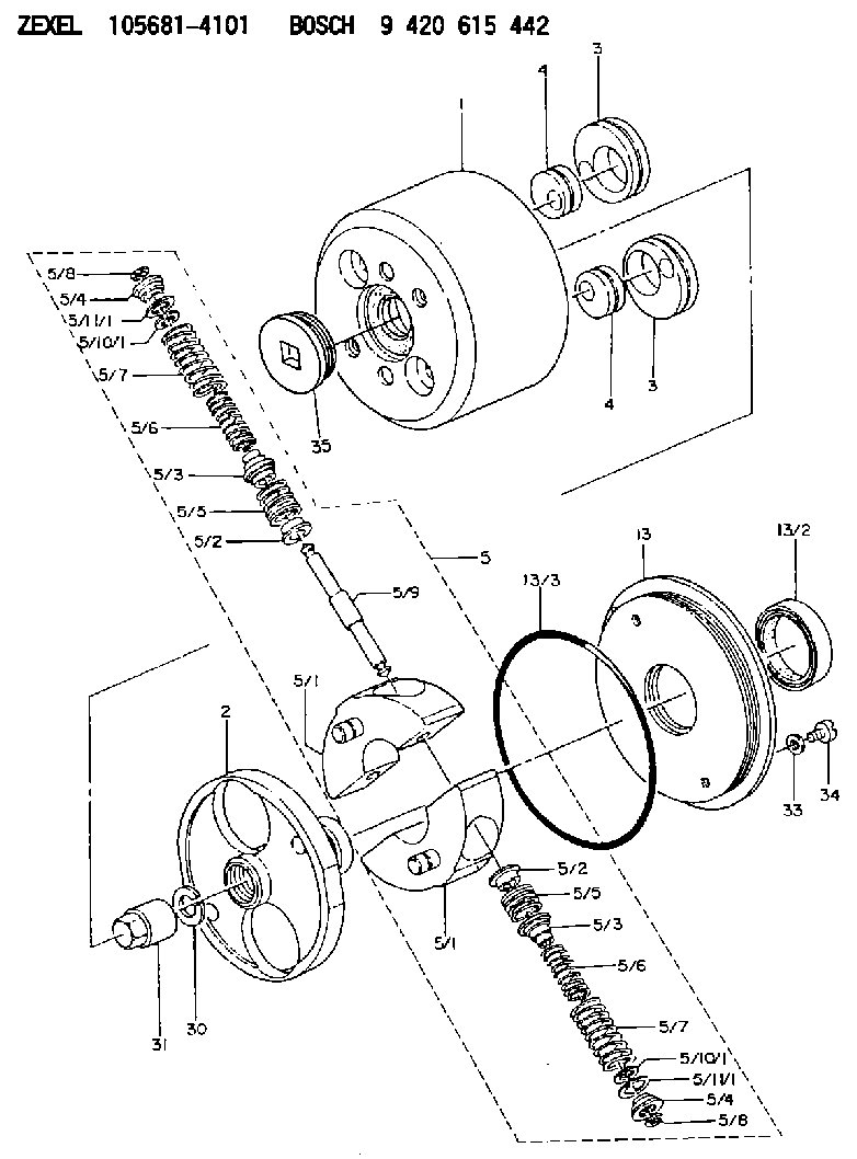
| 1. | [1] | 156800-1520 | TIMING-DEVICE HOUSING |
| 2. | [1] | 156801-2200 | FLANGE BUSHING |
| 3. | [2] | 156723-0300 | ECCENTRIC DISC |
| 3. | [2] | 156723-0300 | ECCENTRIC DISC |
| 4. | [2] | 156723-0400 | ECCENTRIC DISC |
| 4. | [2] | 156723-0400 | ECCENTRIC DISC |
| 5. | [1] | 156818-3920 | FLYWEIGHT ASSEMBLY |
| 5/1. | [2] | 156802-2920 | FLYWEIGHT |
| 5/1. | [2] | 156802-2920 | FLYWEIGHT |
| 5/2. | [4] | 156807-0800 | SLOTTED WASHER |
| 5/2. | [4] | 156807-0800 | SLOTTED WASHER |
| 5/3. | [4] | 156727-0200 | SLOTTED WASHER |
| 5/3. | [4] | 156727-0200 | SLOTTED WASHER |
| 5/4. | [4] | 156807-1200 | SLOTTED WASHER |
| 5/4. | [4] | 156807-1200 | SLOTTED WASHER |
| 5/5. | [4] | 156816-2600 | COMPRESSION SPRING |
| 5/5. | [4] | 156816-2600 | COMPRESSION SPRING |
| 5/6. | [4] | 156815-6000 | COMPRESSION SPRING |
| 5/6. | [4] | 156815-6000 | COMPRESSION SPRING |
| 5/7. | [4] | 156814-7500 | COMPRESSION SPRING |
| 5/7. | [4] | 156814-7500 | COMPRESSION SPRING |
| 5/8. | [4] | 156729-0500 | LOCKING WASHER |
| 5/8. | [4] | 156729-0500 | LOCKING WASHER |
| 5/9. | [2] | 156806-0121 | PIN |
| 5/10/1. | [0] | 156728-0800 | SHIM D19&15T0.1 |
| 5/10/1. | [0] | 156728-0800 | SHIM D19&15T0.1 |
| 5/10/1. | [0] | 156728-0900 | SHIM D19&15T0.3 |
| 5/10/1. | [0] | 156728-1000 | SHIM D19&15T0.5 |
| 5/10/1. | [0] | 156728-1100 | SHIM D19&15T1.0 |
| 5/10/1. | [0] | 156728-2000 | SHIM D19&15T0.4 |
| 5/10/1. | [0] | 156728-2100 | SHIM D19&15T0.7 |
| 13. | [1] | 156809-1620 | COVER |
| 13/2. | [1] | 139648-0300 | PACKING RING |
| 13/3. | [1] | 156315-0200 | O-RING |
| 30. | [1] | 156322-0000 | LOCKING WASHER |
| 31. | [1] | 134325-0800 | UNION NUT |
| 33. | [1] | 029331-0190 | GASKET |
| 34. | [1] | 156316-0000 | CAPSULE |
| 35. | [1] | 156314-0501 | CAP |
Cross reference number
Zexel num
Bosch num
Firm num
Name
105681-4101
AUTOM. ADVANCE MECHANISM
K 14KL AUTOMATIC TIMER TIMER SPG TIMER
K 14KL AUTOMATIC TIMER TIMER SPG TIMER
Information:
Ensure that all components are free of contaminants before installing. Contaminants may cause premature wear and reduced component service life.
Note: Disposition and Recycling - Common components of exhaust aftertreatment devices include, but are not limited to, cordierite, silicon carbide, iron zeolite, vanadium, platinum, and palladium. After the devices are used in an engine exhaust flow they can include some by-products that result from combustion. Follow applicable Federal, State, and local regulations when handling or discarding used aftertreatment devices
Illustration 1 g03842051
Note: Prior to removal of the catalyst, identify the position of the catalysts and airflow direction. Ensure that the catalyst part number position and the air flow direction remain the same.
Remove Diesel Particulate Filter (DPF) hatch cover (1) nuts, bolts, and washers.
Remove hatch cover (1) from the reactor unit.
Remove gasket assembly from the sealing surface of the hatch cover.
Carefully remove DPF catalyst assembly by removing the V band clamps. If necessary, repeat for other PDF catalysts. Take note of DPF air flow direction and location for reassembly.
Carefully install DPF catalyst into the cabinet with new gaskets. Verify correct position and air flow direction of the DPF.
DPF should always be installed in the direction shown in illustration 1. The long end of the DPF should be installed in the sleeve of the reactor and secured with the proper V band clamps.
For verified applications, replacement DPFs must have the proper tags and meet all documentation requirements.
Apply final torque to V band clamps. Refer to Specifications, SENR3130, "Torque Specifications" for the proper torque.
Replace all inner backing strip gaskets on the DPF catalyst cover.
Install DPF cover assembly.
Replace all damaged bolts.
Apply final torque to all bolts in a circular pattern. Refer to Specifications, SENR3130, "Torque Specifications" for the proper torque.
Verify that all bolts are at the proper torque value.