Information autom. advance mechanism
BOSCH
9 420 616 075
9420616075
ZEXEL
105681-2390
1056812390
MITSUBISHI
ME742722
me742722
Rating:
Scheme ###:
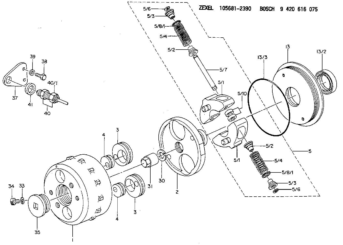
| 1. | [1] | 156800-4520 | TIMING-DEVICE HOUSING |
| 2. | [1] | 156801-5300 | FLANGE BUSHING |
| 3. | [2] | 156723-0300 | ECCENTRIC DISC |
| 3. | [2] | 156723-0300 | ECCENTRIC DISC |
| 4. | [2] | 156723-0400 | ECCENTRIC DISC |
| 4. | [2] | 156723-0400 | ECCENTRIC DISC |
| 5. | [1] | 156898-1020 | FLYWEIGHT ASSEMBLY |
| 5/1. | [2] | 156802-5320 | FLYWEIGHT |
| 5/1. | [2] | 156802-5320 | FLYWEIGHT |
| 5/2. | [4] | 156807-1100 | SLOTTED WASHER |
| 5/2. | [4] | 156807-1100 | SLOTTED WASHER |
| 5/3. | [4] | 156807-0900 | SLOTTED WASHER |
| 5/3. | [4] | 156807-0900 | SLOTTED WASHER |
| 5/4. | [4] | 156896-9100 | COMPRESSION SPRING |
| 5/4. | [4] | 156896-9100 | COMPRESSION SPRING |
| 5/6. | [4] | 156809-0300 | LOCKING WASHER |
| 5/6. | [4] | 156809-0300 | LOCKING WASHER |
| 5/7. | [2] | 156806-0900 | PIN |
| 5/8/1. | [0] | 156728-0800 | SHIM D19&15T0.1 |
| 5/8/1. | [0] | 156728-0900 | SHIM D19&15T0.3 |
| 5/8/1. | [0] | 156728-1000 | SHIM D19&15T0.5 |
| 5/8/1. | [0] | 156728-1100 | SHIM D19&15T1.0 |
| 5/8/1. | [0] | 156728-2000 | SHIM D19&15T0.4 |
| 5/8/1. | [0] | 156728-2100 | SHIM D19&15T0.7 |
| 5/8/1. | [0] | 156728-2100 | SHIM D19&15T0.7 |
| 5/10. | [4] | 156808-0500 | SPACER BUSHING |
| 13. | [1] | 156809-1620 | COVER |
| 13/2. | [1] | 139648-0300 | PACKING RING |
| 13/3. | [1] | 156315-0200 | O-RING |
| 30. | [1] | 156322-0000 | LOCKING WASHER |
| 31. | [1] | 134325-0800 | UNION NUT |
| 33. | [1] | 029331-0190 | GASKET D14&10.2T1 |
| 34. | [1] | 156316-0000 | CAPSULE |
| 35. | [1] | 156314-0501 | CAP |
| 37. | [1] | 156914-1500 | PLATE |
| 38. | [2] | 020118-1640 | BLEEDER SCREW |
| 39. | [2] | 014020-8140 | PLAIN WASHER D16&8.5T1.2 |
| 40. | [1] | 479770-8220 | PULSE GENERATOR |
| 40/1. | [1] | 479770-8200 | PULSE GENERATOR |
| 41. | [1] | 139316-0000 | PLAIN WASHER D25&16.5T5 |
Include in #1:
107691-2610
as AUTOM. ADVANCE MECHANIS
Cross reference number
Zexel num
Bosch num
Firm num
Name
Information:
Use the following procedure to update the fuel lines group with the new hose assemblies.Note: Follow all the safety precautions before carrying out any work on the machine.Installation of 488-9360 Hose As between Fuel Tank and Primary filter group
Illustration 1 g06107286
View of inner side of left-hand frame
(A) Fuel tank
(1) 488-9360 Hose As
(2) 383-6118 Clip
Remove former 236-5242 Hose As from fuel tank (A) along the left-hand inner frame and replace with 488-9360 Hose As (1). Use two 383-6118 Clips (2) to mount 488-9360 Hose As (1) to the inner frame.
Illustration 2 g06107793
View of hose routing above the steering box assembly
(1) 488-9360 Hose As
(3) 6D-4244 Clip
Continue routing 488-9360 Hose As (1) above the steering box assembly from left to right using two 6D-4244 Clips (3) in place of the former 1S-0994 Clips.
Illustration 3 g06107808
View of hose routing to the primary filter group
(1) 488-9360 Hose As
(3) 6D-4244 Clips
Route 488-9360 Hose As (1) along the frame and up toward the primary filter group using 6D-4244 Clips (3) to secure to the frame.
Illustration 4 g06108256
View of primary filter group location inner side of right-hand frame
(B) Former fitting
(C) Primary filter group
(1) 488-9360 Hose As
(4) 148-8354 Elbow As
If not previously completed, remove former hose (B) along with the related fitting from the connection on primary filter group (C).
Connect 148-8354 Elbow As (4) onto primary filter group (C) where fitting (B) was removed.
Attach 488-9360 Hose As (1) to 148-8354 Elbow As (4).Installation of 488-9362 Hose As Between Fuel Tank and Fuel Return Manifold
Illustration 5 g06108268
View of left inner frame
(D) Former hose 240-8598 Hose As
Remove former return hose assembly (D) from between the fuel tank and the fuel manifold in the engine.Note: Unless specified otherwise, retain all mounting hardware for reuse.
Illustration 6 g06108327
View of new hose route.
(A) Fuel tank
(2) 383-6118 Clip
(5) 488-9362 Hose As
Connect 488-9362 Hose As (5) to fuel tank where the old hose was removed.
Route 488-9362 Hose As (5) back along the left-hand inner frame towards the engine and use two 383-6118 Clips (2) installed previously to secure hose assembly (5) in place.
Illustration 7 g06112935
View of the rear of the engine
(5) 488-9362 Hose As
(6) 9M-8406 Clip
(7) 329-1681 Clip
Finish installing 488-9362 Hose As (5) by routing hose (5) up the rear side of the engine and connecting the hose where former hose (D) was removed.
Secure 488-9362 Hose As (5) using one 9M-8406 Clip (6) and one 329-1681 Clip (7).Installation of 488-9361 Hose As Between Primary Filter Group and Engine
Illustration 8 g06108399
Top view of the engine underneath the hood
(3) 6D-4244 Clip
(8) 488-9361 Hose As
Remove the existing hose assembly between the primary filter group and the engine.
Install 488-9361 Hose As (8) where the former hose was removed.
Use one 6D-4244 Clip (3) to secure hose assembly (8) to the top of the engine.