Information autom. advance mechanism
BOSCH
9 420 616 941
9420616941
ZEXEL
105681-2370
1056812370
NISSAN-DIESEL
1685196872
1685196872

Rating:
Scheme ###:
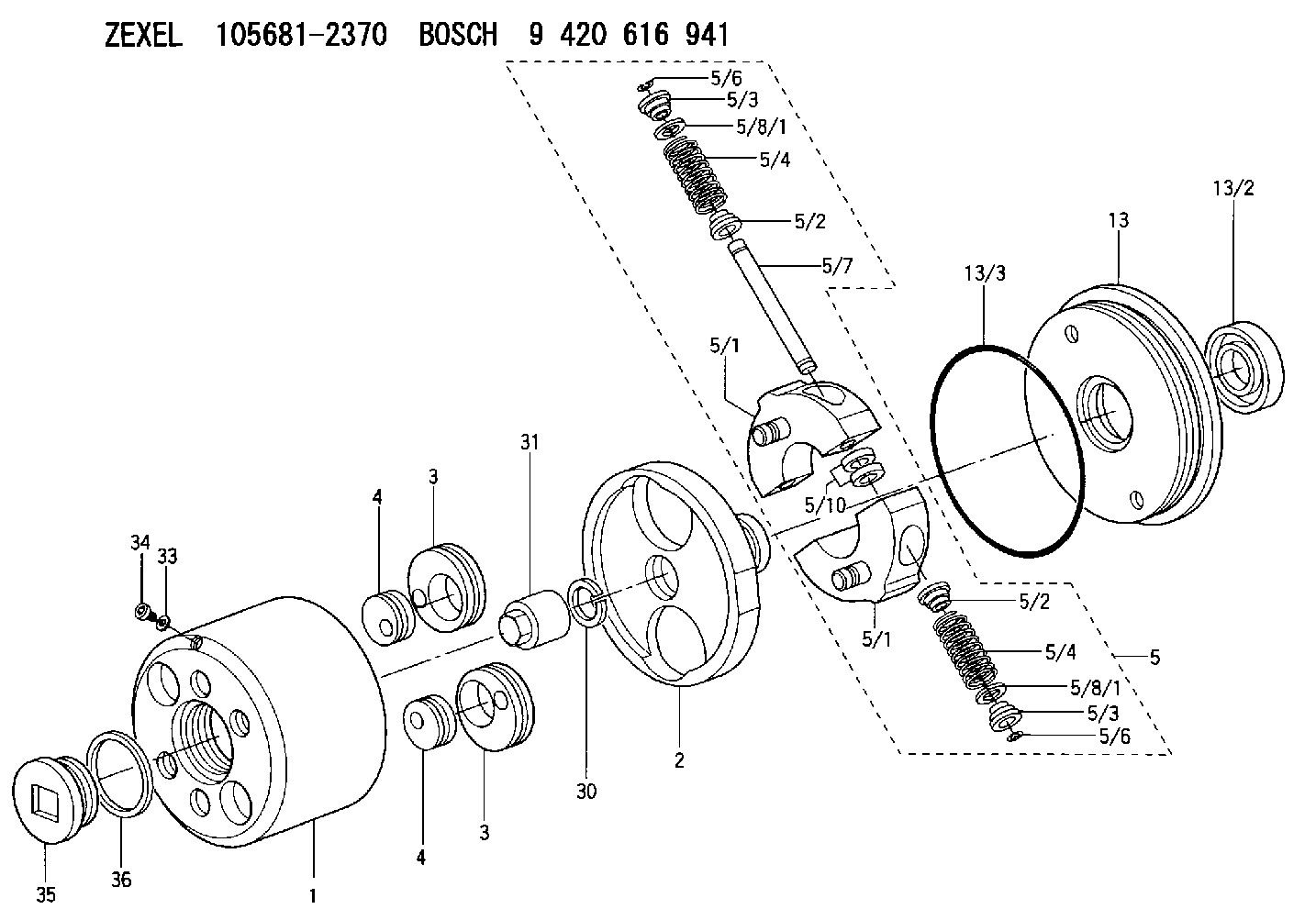
| 1. | [1] | 156800-2420 | TIMING-DEVICE HOUSING |
| 2. | [1] | 156801-2200 | FLANGE BUSHING |
| 3. | [2] | 156723-0300 | ECCENTRIC DISC |
| 3. | [2] | 156723-0300 | ECCENTRIC DISC |
| 4. | [2] | 156723-0400 | ECCENTRIC DISC |
| 4. | [2] | 156723-0400 | ECCENTRIC DISC |
| 5. | [1] | 156898-0620 | FLYWEIGHT ASSEMBLY |
| 5/1. | [2] | 156802-7620 | FLYWEIGHT |
| 5/1. | [2] | 156802-7620 | FLYWEIGHT |
| 5/2. | [4] | 156807-1100 | SLOTTED WASHER |
| 5/2. | [4] | 156807-1100 | SLOTTED WASHER |
| 5/3. | [4] | 156807-1000 | SLOTTED WASHER |
| 5/3. | [4] | 156807-1000 | SLOTTED WASHER |
| 5/4. | [4] | 156896-8300 | COMPRESSION SPRING |
| 5/4. | [4] | 156896-8300 | COMPRESSION SPRING |
| 5/6. | [4] | 156809-0300 | LOCKING WASHER |
| 5/6. | [4] | 156809-0300 | LOCKING WASHER |
| 5/7. | [2] | 156806-0900 | PIN |
| 5/8/1. | [0] | 156728-0800 | SHIM D19&15T0.1 |
| 5/8/1. | [0] | 156728-0900 | SHIM D19&15T0.3 |
| 5/8/1. | [0] | 156728-1000 | SHIM D19&15T0.5 |
| 5/8/1. | [0] | 156728-1100 | SHIM D19&15T1.0 |
| 5/8/1. | [0] | 156728-2000 | SHIM D19&15T0.4 |
| 5/8/1. | [0] | 156728-2100 | SHIM D19&15T0.7 |
| 5/8/1. | [0] | 156728-2400 | SHIM D19&15T0.6 |
| 5/8/1. | [0] | 156728-2500 | SHIM D19&15T0.8 |
| 5/8/1. | [0] | 156728-2600 | SHIM D19&15T0.9 |
| 5/8/1. | [0] | 156728-2600 | SHIM D19&15T0.9 |
| 5/10. | [4] | 156808-0500 | SPACER BUSHING |
| 13. | [1] | 156809-2620 | COVER |
| 13/2. | [1] | 139648-0600 | PACKING RING |
| 13/3. | [1] | 156315-0200 | O-RING |
| 30. | [1] | 156322-0000 | LOCKING WASHER |
| 31. | [1] | 134325-0800 | UNION NUT |
| 33. | [1] | 029331-0190 | GASKET D14&10.2T1 |
| 34. | [1] | 156316-0000 | CAPSULE |
| 35. | [1] | 156314-0600 | CAP |
| 36. | [1] | 156319-0200 | GASKET |
Cross reference number
Zexel num
Bosch num
Firm num
Name
105681-2370
1685196872 NISSAN-DIESEL
AUTOM. ADVANCE MECHANISM
K 14KL AUTOMATIC TIMER TIMER SPG TIMER
K 14KL AUTOMATIC TIMER TIMER SPG TIMER
Information:
Introduction
Do not perform any procedure in this Special Instruction until you have read the information and you understand the information.Required Tools
Table 1
Part Number Part Name Qty
- Flat-head screwdriver 1 Replacement Procedure
Illustration 1 g06099930
(1) Connector housing
(2) DCU
(3) Camlock connectors
Locate connector housings (1) on DCU (2). Disconnect the connectors from the DCU.
Illustration 2 g06099944
(1) Connector housing
(3) Camlock connector
(A) Flat-head screwdriver
Use a flat-head screwdriver (A) to pry the tab on the side of connector housing (1) up gently. Pull out on the camlock connector to disengage the locking tab.
Flip connector housing (1) over to the opposite side. Use a flat-head screwdriver (A) to pry the tab on the side of the connector housing up gently. Pull out on the camlock connector to disengage the locking tab.
Illustration 3 g06099938
(1) Connector housing
(3) Camlock connector
Remove camlock connector (3) from connector housing (1).
To install the new camlock connector (3), slide the camlock connector into connector housing (1). Once the camlock is pushed past the locking tabs, the camlock connector will be held in place.