Information autom. advance mechanism
BOSCH
9 420 616 186
9420616186
ZEXEL
105681-2060
1056812060
ISUZU
1157404970
1157404970

Rating:
Scheme ###:
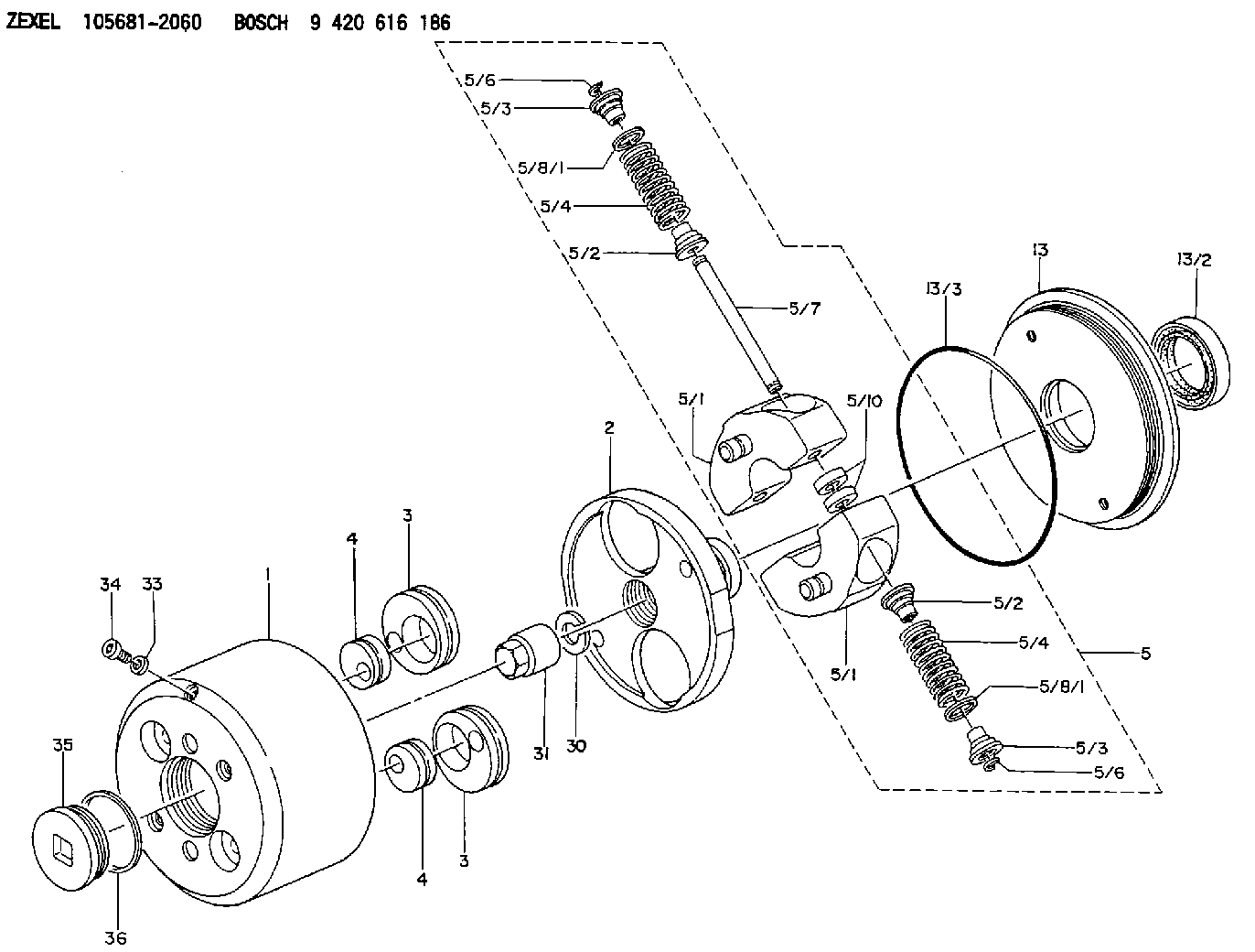
| 1. | [1] | 156800-2620 | TIMING-DEVICE HOUSING |
| 2. | [1] | 156801-3400 | FLANGE BUSHING |
| 3. | [2] | 156723-0300 | ECCENTRIC DISC |
| 3. | [2] | 156723-0300 | ECCENTRIC DISC |
| 4. | [2] | 156723-0400 | ECCENTRIC DISC |
| 4. | [2] | 156723-0400 | ECCENTRIC DISC |
| 5. | [1] | 156819-6320 | FLYWEIGHT ASSEMBLY |
| 5/1. | [2] | 156802-6220 | FLYWEIGHT |
| 5/1. | [2] | 156802-6220 | FLYWEIGHT |
| 5/2. | [4] | 156807-1100 | SLOTTED WASHER |
| 5/2. | [4] | 156807-1100 | SLOTTED WASHER |
| 5/3. | [4] | 156807-0900 | SLOTTED WASHER |
| 5/3. | [4] | 156807-0900 | SLOTTED WASHER |
| 5/4. | [4] | 156895-0800 | COMPRESSION SPRING |
| 5/4. | [4] | 156895-0800 | COMPRESSION SPRING |
| 5/6. | [4] | 156809-0300 | LOCKING WASHER |
| 5/6. | [4] | 156809-0300 | LOCKING WASHER |
| 5/7. | [2] | 156806-0900 | PIN |
| 5/8/1. | [0] | 156728-0800 | SHIM D19&15T0.1 |
| 5/8/1. | [0] | 156728-0900 | SHIM D19&15T0.3 |
| 5/8/1. | [0] | 156728-1000 | SHIM D19&15T0.5 |
| 5/8/1. | [0] | 156728-1000 | SHIM D19&15T0.5 |
| 5/8/1. | [0] | 156728-1100 | SHIM D19&15T1.0 |
| 5/8/1. | [0] | 156728-2000 | SHIM D19&15T0.4 |
| 5/8/1. | [0] | 156728-2100 | SHIM D19&15T0.7 |
| 5/10. | [4] | 156808-0500 | SPACER BUSHING |
| 13. | [1] | 156809-1620 | COVER |
| 13/2. | [1] | 139648-0300 | PACKING RING |
| 13/3. | [1] | 156315-0200 | O-RING |
| 30. | [1] | 156322-0000 | LOCKING WASHER |
| 31. | [1] | 134325-0800 | UNION NUT |
| 33. | [1] | 029331-0190 | GASKET D14&10.2T1 |
| 34. | [1] | 156316-0000 | CAPSULE |
| 35. | [1] | 156314-0600 | CAP |
| 36. | [1] | 156319-0200 | GASKET |
Cross reference number
Zexel num
Bosch num
Firm num
Name
105681-2060
1157404970 ISUZU
AUTOM. ADVANCE MECHANISM
K 14KL AUTOMATIC TIMER TIMER SPG TIMER
K 14KL AUTOMATIC TIMER TIMER SPG TIMER
Information:
Introduction
Do not perform any procedure in this Special Instruction until you have read this information and you understand this information.Required Parts
Table 1
Required Parts
Item Qty New Part Number Part Name
1 2 137-8101 O-Ring Seal
2 2 286-5030 Elbow
3 1 289-3891 Clip
4 1 294-6118 Pressure Sensor
5 1 356-0920 Bracket
6 2 3J-7352 Connector
7 2 6V-5048 O-Ring Seal
8 2 8T-0267 Bolt
9 2 9X-8267 Washer
10 108-9656 Cable Straps
11 2 5P-1717 Hose Clamp
12 1 356-6802 Sensor Harness As
13 1 289-3891 Clip
14 2 5P-3860 Hose Clamp Procedure
Illustration 1 g02082554
Example of a vertical filter group (1) Connection for the pressure sensor group (2) New bypass wiring harness (3) Connection for the mounted sensor group (4) OEM wiring harness connection (5) OEM wiring harness (6) Wire for the probe of the outlet temperature is secured to the new P1 tube. (7) Support bracket for the new P1 tube (8) New P1 tube (9) The wire for the probe for the inlet temperature is secured to new P1 tube. (10) New P2 tubeNote: Avoid placing