Information autom. advance mechanism
BOSCH
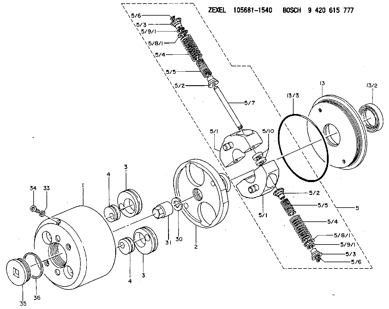
9 420 615 777
9420615777
ZEXEL
105681-1540
1056811540

Rating:
Scheme ###:
| 1. | [1] | 156800-2620 | TIMING-DEVICE HOUSING |
| 1. | [1] | 156800-2620 | TIMING-DEVICE HOUSING |
| 2. | [1] | 156801-2601 | FLANGE BUSHING |
| 2. | [1] | 156801-2601 | FLANGE BUSHING |
| 3. | [2] | 156723-0300 | ECCENTRIC DISC |
| 3. | [2] | 156723-0300 | ECCENTRIC DISC |
| 3. | [2] | 156723-0300 | ECCENTRIC DISC |
| 3. | [2] | 156723-0300 | ECCENTRIC DISC |
| 4. | [2] | 156723-0400 | ECCENTRIC DISC |
| 4. | [2] | 156723-0400 | ECCENTRIC DISC |
| 4. | [2] | 156723-0400 | ECCENTRIC DISC |
| 4. | [2] | 156723-0400 | ECCENTRIC DISC |
| 5. | [1] | 156819-9920 | FLYWEIGHT ASSEMBLY |
| 5. | [1] | 156819-9920 | FLYWEIGHT ASSEMBLY |
| 5/1. | [2] | 156802-0820 | FLYWEIGHT |
| 5/1. | [2] | 156802-0820 | FLYWEIGHT |
| 5/1. | [2] | 156802-0820 | FLYWEIGHT |
| 5/1. | [2] | 156802-0820 | FLYWEIGHT |
| 5/2. | [4] | 156807-1100 | SLOTTED WASHER |
| 5/2. | [4] | 156807-1100 | SLOTTED WASHER |
| 5/2. | [4] | 156807-1100 | SLOTTED WASHER |
| 5/2. | [4] | 156807-1100 | SLOTTED WASHER |
| 5/3. | [4] | 156807-0900 | SLOTTED WASHER |
| 5/3. | [4] | 156807-0900 | SLOTTED WASHER |
| 5/3. | [4] | 156807-0900 | SLOTTED WASHER |
| 5/3. | [4] | 156807-0900 | SLOTTED WASHER |
| 5/4. | [4] | 156817-9200 | COMPRESSION SPRING |
| 5/4. | [4] | 156817-9200 | COMPRESSION SPRING |
| 5/4. | [4] | 156817-9200 | COMPRESSION SPRING |
| 5/4. | [4] | 156817-9200 | COMPRESSION SPRING |
| 5/5. | [4] | 156815-3400 | COMPRESSION SPRING |
| 5/5. | [4] | 156815-3400 | COMPRESSION SPRING |
| 5/5. | [4] | 156815-3400 | COMPRESSION SPRING |
| 5/5. | [4] | 156815-3400 | COMPRESSION SPRING |
| 5/6. | [4] | 156809-0300 | LOCKING WASHER |
| 5/6. | [4] | 156809-0300 | LOCKING WASHER |
| 5/6. | [4] | 156809-0300 | LOCKING WASHER |
| 5/6. | [4] | 156809-0300 | LOCKING WASHER |
| 5/7. | [2] | 156806-0900 | PIN |
| 5/7. | [2] | 156806-0900 | PIN |
| 5/8/1. | [0] | 156728-0800 | SHIM D19&15T0.1 |
| 5/8/1. | [0] | 156728-0900 | SHIM D19&15T0.3 |
| 5/8/1. | [0] | 156728-1000 | SHIM D19&15T0.5 |
| 5/8/1. | [0] | 156728-1100 | SHIM D19&15T1.0 |
| 5/8/1. | [0] | 156728-2000 | SHIM D19&15T0.4 |
| 5/8/1. | [0] | 156728-2000 | SHIM D19&15T0.4 |
| 5/8/1. | [0] | 156728-2000 | SHIM D19&15T0.4 |
| 5/8/1. | [0] | 156728-2000 | SHIM D19&15T0.4 |
| 5/8/1. | [0] | 156728-2100 | SHIM D19&15T0.7 |
| 5/8/1. | [0] | 156728-2400 | SHIM D19&15T0.6 |
| 5/8/1. | [0] | 156728-2500 | SHIM D19&15T0.8 |
| 5/8/1. | [0] | 156728-2600 | SHIM D19&15T0.9 |
| 5/9/1. | [0] | 156728-1200 | SHIM D14&10.6T0.1 |
| 5/9/1. | [0] | 156728-1200 | SHIM D14&10.6T0.1 |
| 5/9/1. | [0] | 156728-1200 | SHIM D14&10.6T0.1 |
| 5/9/1. | [0] | 156728-1200 | SHIM D14&10.6T0.1 |
| 5/9/1. | [0] | 156728-1300 | SHIM D14&10.6T0.3 |
| 5/9/1. | [0] | 156728-1400 | SHIM D14&10.6T0.5 |
| 5/9/1. | [0] | 156728-1500 | SHIM D14&10.6T1.0 |
| 5/9/1. | [0] | 156728-2200 | SHIM D14&10.6T0.4 |
| 5/9/1. | [0] | 156728-2300 | SHIM D14&10.6T0.7 |
| 5/9/1. | [0] | 156728-2700 | SHIM D14&10.6T0.6 |
| 5/9/1. | [0] | 156728-2800 | SHIM D14&10.6T0.8 |
| 5/9/1. | [0] | 156728-2900 | SHIM D14&10.6T0.9 |
| 5/10. | [4] | 156808-0500 | SPACER BUSHING |
| 5/10. | [4] | 156808-0500 | SPACER BUSHING |
| 13. | [1] | 156809-2320 | COVER |
| 13. | [1] | 156809-2320 | COVER |
| 13/2. | [1] | 139648-0300 | PACKING RING |
| 13/2. | [1] | 139648-0300 | PACKING RING |
| 13/3. | [1] | 156315-0200 | O-RING |
| 13/3. | [1] | 156315-0200 | O-RING |
| 30. | [1] | 156322-0000 | LOCKING WASHER |
| 30. | [1] | 156322-0000 | LOCKING WASHER |
| 31. | [1] | 134325-0800 | UNION NUT |
| 31. | [1] | 134325-0800 | UNION NUT |
| 33. | [1] | 029331-0190 | GASKET D14&10.2T1 |
| 33. | [1] | 029331-0190 | GASKET D14&10.2T1 |
| 34. | [1] | 156316-0000 | CAPSULE |
| 34. | [1] | 156316-0000 | CAPSULE |
| 35. | [1] | 156314-0600 | CAP |
| 35. | [1] | 156314-0600 | CAP |
| 36. | [1] | 156319-0200 | GASKET |
| 36. | [1] | 156319-0200 | GASKET |
Include in #1:
106871-4290
as AUTOM. ADVANCE MECHANIS
Cross reference number
Zexel num
Bosch num
Firm num
Name
Information:
Observe the safe working load limits of all lifting and blocking devices and keep a safe distance from suspended/blocked loads. Personnel may be seriously injured or killed by falling loads.
Problem
There have been isolated instances where the Diesel Exhaust Fluid (DEF) pressure sensor within the DEF pump breaks and DEF leaks into the DEF pump. DEF wicks up the wiring between the DEF pump and the interface connector. The DEF then shorts across the pins of the connector leading to the issue.Solution
Do not operate or work on this product unless you have read and understood the instruction and warnings in the relevant Operation and Maintenance Manuals and relevant service literature. Failure to follow the instructions or heed the warnings could result in injury or death. Proper care is your responsibility.
Using an electronic service tool, generate a Product Status Report (PSR) with the engine running histograms and abnormal shutdown history included.
Check to see if the DEF system has been contaminated. Examples of contaminants are fuels, oils, coolant, and wind shield washer fluid.
DEF Injector
Remove electrical connector and examine it for the presence of DEF.
Illustration 1 g06386447
Typical example of a DEF injector
(1) Location of the serial number
(2) DEF injector
(3) DEF injector electrical connectorNote: Do not remove DEF injector from Clean Emissions Module (CEM).
Illustration 2 g06386460
Typical example DEF injector electrical connector
Examine the OEM harness connection for the presence of DEF in the connector.
31-Pin Connector
Illustration 3 g06386503
Typical example of a 31-pin connector
Confirm that the 31-pin connector is securely tightened.
Illustration 4 g06386512
Typical example of a 31-pin connector with blanking caps
(4) Blanking caps
Ensure that blanking caps (4) are in place on the unused pins on both sides 31-pin connector.
Illustration 5 g06388958
Typical example of a 31-pin connector O-Ring location
Disconnect 31-pin connector and ensure that the O-Ring is in the correct position in the machine side of the connection. Position (Y) shows where the red O-Ring seal is located.
Check for fluid contamination in the 31-pin connector. If contaminant is present, determine what the contaminant is. Check for DEF, which leaves white residue marks or the PH level (9 to 9.5).Check for diesel using HC strips. Check for water (PH 7).
Check for signs of overheating or corrosion.
Machine Fuse
Inspect DEF fuse condition and the fuse rating.
DEF Injector
Using a suitable multimeter, measure the electrical resistance on DEF injector connector pin 1 to pin 2. If the measured resistance is less than 6 Ohms or more than 8 Ohms, a fault in the injector is detected.
Check for signs of the presence of DEF within the machine electrical wires connected to the DEF injector.
Check the history of the machine for previous DEF injector issues.
Use the electronic service tool to generate a PSR and obtain an abnormal shutdown, engine running histograms, and application history.
Check for logged 3361-5 or 3821-5 "Aftertreatment #1 DEF Dosing Unit: Current Below Normal" diagnostic codes.
Using a suitable multimeter, measure the resistance between the following points:
31-pin connector pin 11 and pin 2 DEF injector connector.
31-pin connector pin 12 and pin 1 DEF injector connector.
If the measured resistance is greater than 2 Ohms. There is an open