Information autom. advance mechanism
BOSCH
9 420 615 606
9420615606
ZEXEL
105681-1000
1056811000
MITSUBISHI
ME727945
me727945
Rating:
Scheme ###:
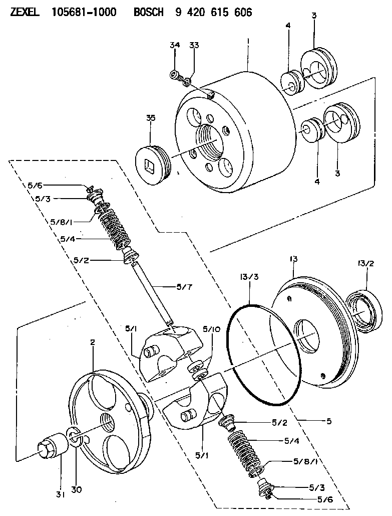
| 1. | [1] | 156800-0920 | TIMING-DEVICE HOUSING |
| 2. | [1] | 156801-2601 | FLANGE BUSHING |
| 3. | [2] | 156723-0300 | ECCENTRIC DISC |
| 3. | [2] | 156723-0300 | ECCENTRIC DISC |
| 4. | [2] | 156723-0400 | ECCENTRIC DISC |
| 4. | [2] | 156723-0400 | ECCENTRIC DISC |
| 5. | [1] | 156818-3320 | FLYWEIGHT ASSEMBLY |
| 5/1. | [2] | 156802-0720 | FLYWEIGHT |
| 5/1. | [2] | 156802-0720 | FLYWEIGHT |
| 5/2. | [4] | 156807-1100 | SLOTTED WASHER |
| 5/2. | [4] | 156807-1100 | SLOTTED WASHER |
| 5/3. | [4] | 156807-0900 | SLOTTED WASHER |
| 5/3. | [4] | 156807-0900 | SLOTTED WASHER |
| 5/4. | [4] | 156816-0800 | COMPRESSION SPRING |
| 5/4. | [4] | 156816-0800 | COMPRESSION SPRING |
| 5/6. | [4] | 156809-0300 | LOCKING WASHER |
| 5/6. | [4] | 156809-0300 | LOCKING WASHER |
| 5/7. | [2] | 156806-0900 | PIN |
| 5/8/1. | [0] | 156728-0800 | SHIM D19&15T0.1 |
| 5/8/1. | [0] | 156728-0900 | SHIM D19&15T0.3 |
| 5/8/1. | [0] | 156728-1000 | SHIM D19&15T0.5 |
| 5/8/1. | [0] | 156728-1100 | SHIM D19&15T1.0 |
| 5/8/1. | [0] | 156728-2000 | SHIM D19&15T0.4 |
| 5/8/1. | [0] | 156728-2000 | SHIM D19&15T0.4 |
| 5/8/1. | [0] | 156728-2100 | SHIM D19&15T0.7 |
| 5/10. | [4] | 156808-0500 | SPACER BUSHING |
| 13. | [1] | 156809-1620 | COVER |
| 13/2. | [1] | 139648-0300 | PACKING RING |
| 13/3. | [1] | 156315-0200 | O-RING |
| 30. | [1] | 156322-0000 | LOCKING WASHER |
| 31. | [1] | 134325-0800 | UNION NUT |
| 33. | [1] | 029331-0190 | GASKET D14&10.2T1 |
| 34. | [1] | 156316-0000 | CAPSULE |
| 35. | [1] | 156314-0501 | CAP |
Include in #1:
106873-2331
as AUTOM. ADVANCE MECHANIS
Cross reference number
Zexel num
Bosch num
Firm num
Name
105681-1000
ME727945 MITSUBISHI
AUTOM. ADVANCE MECHANISM
K 14KL AUTOMATIC TIMER TIMER SPG TIMER
K 14KL AUTOMATIC TIMER TIMER SPG TIMER
Information:
The Caterpillar Electronic Technician (ET)
Illustration 1 g00777826
The Caterpillar Electronic Technician (ET) is a software program that is used to access data. The service technician can use the Caterpillar Electronic Technician in order to perform maintenance work on the machine. Some of the options that are available with the Caterpillar Electronic Technician are listed below:
View Diagnostic codes. See Troubleshooting, "Using the Caterpillar Electronic Technician to Determine Diagnostic Codes".
View the status of parameters.
Clear active diagnostic codes and clear logged diagnostic codes
Perform calibration of machine systems.
Program the ECM (Flash). This is done with the "WINflash" program. See Testing and Adjusting, "Electronic Control Module (ECM) - Flash Program".
Print reports.The following list contains some of the diagnostic functions and programming functions that are performed by the service tools.
The failures of the ECM system are displayed.
The status of most of the inputs and the outputs are displayed.
The settings for the ECM are displayed.
Display the status of the input and output parameters in real time.
Display the clock hour of the internal diagnostic clock.
The number of occurrences and the clock hour of the first occurrence and the last occurrence is displayed for each logged diagnostic code.
The definition for each logged diagnostic code and each event is displayed.
Load new FLASH software.See Troubleshooting, "Diagnostic Code List" for the list of diagnostic codes for the ECM.See Troubleshooting, "Using the Caterpillar Electronic Technician to Determine Diagnostic Codes". Diagnostic information is accessed with the following drop down menus:
Active diagnostic codes
Logged diagnostic codesSensor Diagnostics
The following tables show the conditions that the diagnostic codes are set for each sensor. If any of the diagnostic codes are active, the System Problem for the LED will be turned on. During the Debounce time, the affected parameter will remain at the last good value. After the Debounce time, the affected parameter will be set to the default value. Refer to Table 1.
Table 1
Sensor Sample Period (mS) Too Low Too High Defaults
Inlet Pressure (gauge) Code Condition Debounce Code Condition Debounce NA
1 81-4 Input < 0.5 VDC 5 sec on
5 sec off 81-3 Input greater than 4.5 VDC 5 sec on
5 sec off NA
Exhaust Temperature 1 535-4 Input < 1.5 VDC 5 sec on
5 sec off 535-3 Input greater than 4.0 VDC 5 sec on
5 sec off NA Temperature Sensor
Table 2 refers to the properties of the temperature sensor.
Table 2
Function Part Number Measure Range Output Accuracy Power Supply Sensor Mounting Mating
Exhaust Temperature 280-3921
50 °C (122 °F)to
850 °C (1562 °F) N/A
500° 5°C (932° 9°F) to
850° 5°C (1562° 9°F) 5V (+/- 0.5) Thread Size: M14 X 1.5
Probe Length:
70 mm (2.7559 inch) from flange to tip 230-5008 Connector Plug As Pressure Sensor
Table 3
Function PN Max Pressure Measure Burst Pressure Power