Information autom. advance mechanism
BOSCH
9 420 615 960
9420615960
ZEXEL
105681-0621
1056810621
Rating:
Scheme ###:
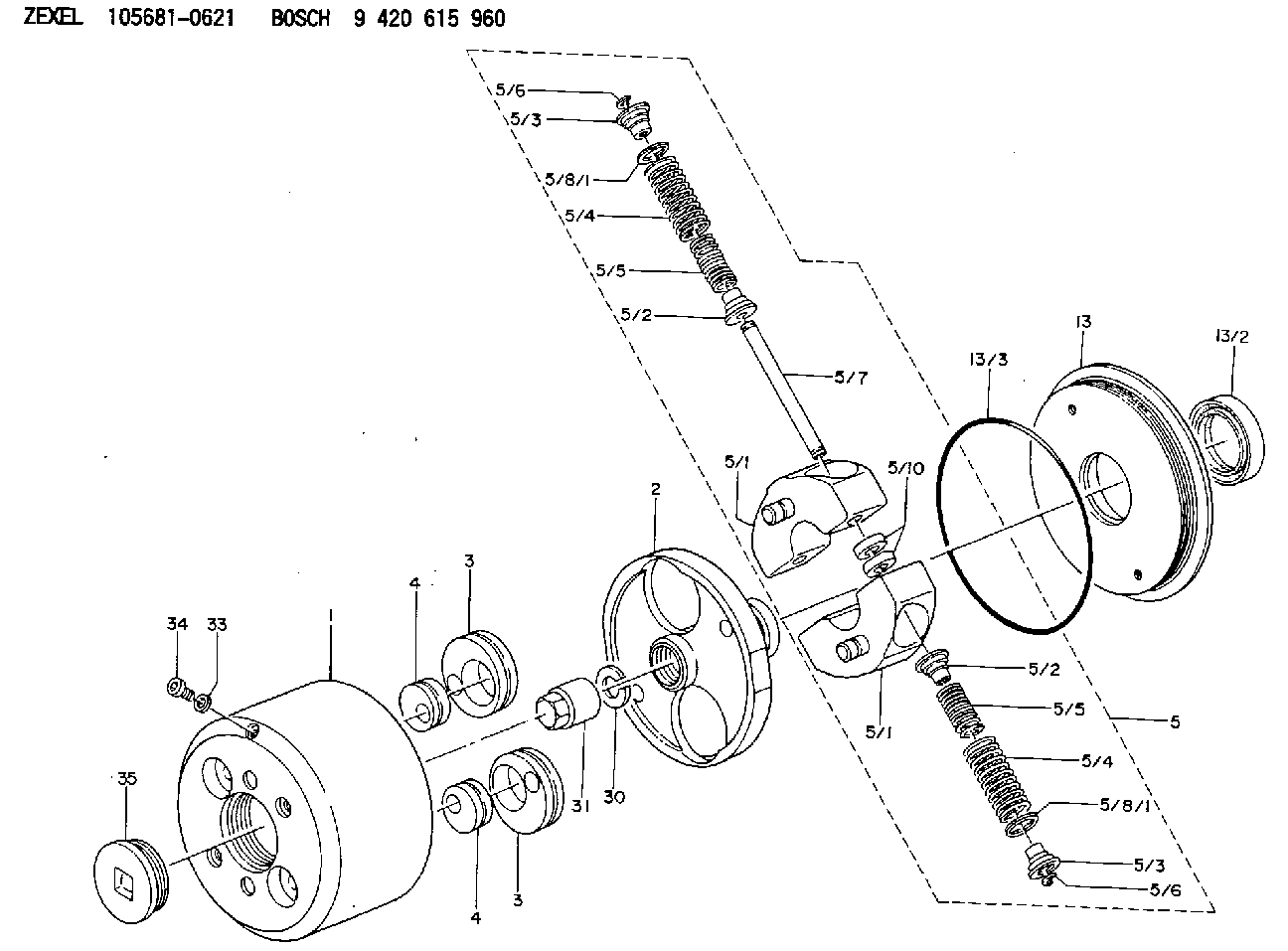
| 1. | [1] | 156800-0920 | TIMING-DEVICE HOUSING |
| 2. | [1] | 156801-2200 | FLANGE BUSHING |
| 3. | [2] | 156723-0300 | ECCENTRIC DISC |
| 3. | [2] | 156723-0300 | ECCENTRIC DISC |
| 4. | [2] | 156723-0400 | ECCENTRIC DISC |
| 4. | [2] | 156723-0400 | ECCENTRIC DISC |
| 5. | [1] | 156810-9020 | FLYWEIGHT ASSEMBLY |
| 5/1. | [2] | 156802-0520 | FLYWEIGHT |
| 5/1. | [2] | 156802-0520 | FLYWEIGHT |
| 5/2. | [4] | 156807-1100 | SLOTTED WASHER |
| 5/2. | [4] | 156807-1100 | SLOTTED WASHER |
| 5/3. | [4] | 156807-0900 | SLOTTED WASHER |
| 5/3. | [4] | 156807-0900 | SLOTTED WASHER |
| 5/4. | [4] | 156814-4200 | COMPRESSION SPRING |
| 5/4. | [4] | 156814-4200 | COMPRESSION SPRING |
| 5/5. | [4] | 156814-4300 | COMPRESSION SPRING |
| 5/5. | [4] | 156814-4300 | COMPRESSION SPRING |
| 5/6. | [4] | 156809-0300 | LOCKING WASHER |
| 5/6. | [4] | 156809-0300 | LOCKING WASHER |
| 5/7. | [2] | 156806-0900 | PIN |
| 5/8/1. | [0] | 156728-0800 | SHIM D19&15T0.1 |
| 5/8/1. | [0] | 156728-0900 | SHIM D19&15T0.3 |
| 5/8/1. | [0] | 156728-0900 | SHIM D19&15T0.3 |
| 5/8/1. | [0] | 156728-1000 | SHIM D19&15T0.5 |
| 5/8/1. | [0] | 156728-1100 | SHIM D19&15T1.0 |
| 5/8/1. | [0] | 156728-2000 | SHIM D19&15T0.4 |
| 5/8/1. | [0] | 156728-2100 | SHIM D19&15T0.7 |
| 5/10. | [4] | 156808-0500 | SPACER BUSHING |
| 13. | [1] | 156809-1620 | COVER |
| 13/2. | [1] | 139648-0300 | PACKING RING |
| 13/3. | [1] | 156315-0200 | O-RING |
| 30. | [1] | 156322-0000 | LOCKING WASHER |
| 31. | [1] | 134325-0800 | UNION NUT |
| 33. | [1] | 029331-0190 | GASKET D14&10.2T1 |
| 34. | [1] | 156316-0000 | CAPSULE |
| 35. | [1] | 156314-0501 | CAP |
Cross reference number
Zexel num
Bosch num
Firm num
Name
Information:
Additional Parts Needed for Installation
Fluid Property Sensor Mounting Bracket
A mounting bracket must be fabricated to support the Fluid Property Sensor. Since the kit can be used on a large range of engines in both stationary and machine applications, no universal mounting bracket design is possible. A bracket must be field fabricated to allow mounting of the sensor to a structural component of the machine. Leave room for electrical connection and room at each end for Engine Lubricating Oil line connections.Fittings and Adapters
Due to the large range of engines that this system may be used on, a list of all Engine Lubrication Oil line fittings, sizes, styles, and adapters are not possible. As a starting point, the inlet and outlet of the sensor adapter is a 37 degree Flare for 1" oil lines. This must be adapted to the correct size oil line tubing required for each engine. It is likely that the supply and return fuel lines will be of different sizes. It is recommended that the oil line tubing be new and in good condition. The tubing MUST be clean inside. Any small particles that are carried from the inlet hose through the transducer from the system and dislodge the particles. If hoses are equipped with O-ring fittings, the O-rings must be new.Wiring Diagram
Note: During Installation, it is important to protect wiring in key locations. Key locations are any area where the wiring could be nicked or cut and come in contact with the chassis. Avoid installation practices where there could be excessive flexing, chafing, or cutting of the wiring.
Illustration 1 g06137996
Fluid Property Sensor Wiring Schematic
Installation
Machine Preparation
Move the machine to a smooth, level location, and away from other working machines and personnel.
Lower the implements to the ground.
Stop the engine.
Engage the parking brake for the machine.
Place the disconnect switch in the OFF position.
Follow all LOTO instructions for the machine.Installation of the Fluid Property Sensor
The Fluid Property Sensor must be located on a field fabricated bracket in a location of the installer's choice. When selecting a mounting location, the installer must mount the sensor in an area off the engine to reduce vibration of the sensor as well as accessibility of sensor and electrical connection. Electrical connections should avoid sharp bends at connectors, sharp edges, and chafing surfaces. Harnesses should be supported at no less than 30.48 cm (12 inch) intervals. The Fluid Property Sensor must be installed with the orifice opening in the upright position as shown in Illustration 2.
Illustration 2 g06138010
Fluid Property Sensor Installation
(A) Oil Pump
(B) Oil Filter
(C) Engine Oil Gallery
(D) Isolation Valve
(E) Oil Flow
(F) Fluid Property Sensor Orientation
(G) Oil Reservoir
(H) Oil Strainer
(I) Engine Oil SumpInstallation of the Electrical Harnesses
Note: During installation, it is important to protect wiring in key locations. Key locations are any area where the wiring could be nicked or cut and come in contact with the chassis. Avoid installation practices where there could be excessive flexing, chafing, or cutting of the wiring.
Install the 514-3811 Instl GP-Field (Fluid Property Harness) on Fluid Property Sensor.
Route harness back