Information autom. advance mechanism
BOSCH
9 420 616 459
9420616459
ZEXEL
105681-0180
1056810180
Rating:
Scheme ###:
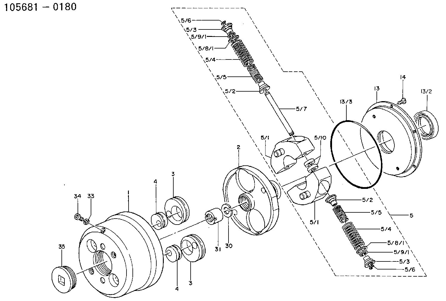
| 1. | [1] | 156800-0720 | TIMING-DEVICE HOUSING |
| 2. | [1] | 156801-1202 | FLANGE BUSHING |
| 3. | [2] | 156723-0300 | ECCENTRIC DISC |
| 3. | [2] | 156723-0300 | ECCENTRIC DISC |
| 4. | [2] | 156723-0400 | ECCENTRIC DISC |
| 4. | [2] | 156723-0400 | ECCENTRIC DISC |
| 5. | [1] | 156810-2421 | FLYWEIGHT ASSEMBLY |
| 5/1. | [2] | 156802-2620 | FLYWEIGHT |
| 5/1. | [2] | 156802-2620 | FLYWEIGHT |
| 5/2. | [4] | 156807-1100 | SLOTTED WASHER |
| 5/2. | [4] | 156807-1100 | SLOTTED WASHER |
| 5/3. | [4] | 156807-0900 | SLOTTED WASHER |
| 5/3. | [4] | 156807-0900 | SLOTTED WASHER |
| 5/4. | [4] | 156805-2700 | COMPRESSION SPRING |
| 5/4. | [4] | 156805-2700 | COMPRESSION SPRING |
| 5/5. | [4] | 156805-8300 | COMPRESSION SPRING |
| 5/5. | [4] | 156805-8300 | COMPRESSION SPRING |
| 5/6. | [4] | 156809-0300 | LOCKING WASHER |
| 5/6. | [4] | 156809-0300 | LOCKING WASHER |
| 5/7. | [2] | 156806-0900 | PIN |
| 5/8/1. | [0] | 156728-0800 | SHIM D19&15T0.1 |
| 5/8/1. | [0] | 156728-0800 | SHIM D19&15T0.1 |
| 5/8/1. | [0] | 156728-0900 | SHIM D19&15T0.3 |
| 5/8/1. | [0] | 156728-1000 | SHIM D19&15T0.5 |
| 5/8/1. | [0] | 156728-1100 | SHIM D19&15T1.0 |
| 5/8/1. | [0] | 156728-2000 | SHIM D19&15T0.4 |
| 5/8/1. | [0] | 156728-2100 | SHIM D19&15T0.7 |
| 5/9/1. | [0] | 156728-1200 | SHIM D14&10.6T0.1 |
| 5/9/1. | [0] | 156728-1200 | SHIM D14&10.6T0.1 |
| 5/9/1. | [0] | 156728-1300 | SHIM D14&10.6T0.3 |
| 5/9/1. | [0] | 156728-1400 | SHIM D14&10.6T0.5 |
| 5/9/1. | [0] | 156728-1500 | SHIM D14&10.6T1.0 |
| 5/9/1. | [0] | 156728-2200 | SHIM D14&10.6T0.4 |
| 5/9/1. | [0] | 156728-2300 | SHIM D14&10.6T0.7 |
| 5/10. | [4] | 156808-0500 | SPACER BUSHING |
| 13. | [1] | 156809-1720 | COVER |
| 13/2. | [1] | 139648-0300 | PACKING RING |
| 13/3. | [1] | 016511-3010 | O-RING |
| 14. | [6] | 012255-1040 | FLAT-HEAD SCREW M5P0.8L10 |
| 30. | [1] | 156322-0000 | LOCKING WASHER |
| 31. | [1] | 134325-0800 | UNION NUT |
| 33. | [1] | 029331-0190 | GASKET D14&10.2T1 |
| 34. | [1] | 156316-0000 | CAPSULE |
| 35. | [1] | 156314-0501 | CAP |
Cross reference number
Zexel num
Bosch num
Firm num
Name
105681-0180
9 420 616 459
AUTOM. ADVANCE MECHANISM
* K 14KL TIMER SPG TIMER
* K 14KL TIMER SPG TIMER
Information:
Table 2
Specifications for Valve Opening Pressure
Nozzle Assembly Valve Opening Pressure
1W-5829
10300 to 17690 kPa (1500 to 2505 psi)
4W-1819
4W-8483
7E-3969
7N-0449
7W-3710
7W-8043
9N-3979
101-0060
115-3354
122-9007
9L-7883
16560 to 17990 kPa (2400 to 2600 psi)
9L-9263
9N-2366
9L-6969
13090 to 19900 kPa (1900 2900 psi)
9N-3299
9N-3700 If the fuel nozzle is not within specifications, stop the test and do not use the nozzle.Check for Tip Leakage
Close the gauge protector valve (0 to 40,000 kPa (0 to 5,800 psi) gauge).
Flush the fuel nozzle that is being tested by pumping the tester for 3 full strokes.
Open the gauge protector valve (0 to 40,000 kPa (0 to 5,800 psi) gauge).
Use a clean cloth to dry the tip and the body of the fuel injector. All test fluid should be wiped from the nozzle assembly.
A clean cloth should be wrapped around the top of the fuel nozzle in order to absorb any internal return leakage.
Calculate the test pressure that will be used for the tip leakage test.Use the fuel nozzle's valve opening pressure, that has been previously recorded, in order to calculate the test pressure for the nozzle that is being tested.
Subtract a value of 1875 kPa (275 psi) from the valve opening pressure that was previously obtained.
Record the result of the calculation as the test pressure that will be used for the tip leakage test.
Slowly apply the test pressure, that has been calculated in Step 6, to the fuel nozzle.
Close the pump isolator valve.
Hold this test pressure for 10 seconds.
Count the number of drops of test fluid that drips from the nozzle during the duration of the test. Open the pump isolator valve in order to release the pressure on the fuel nozzle when the test is completed.Refer to the information that is provided in Table 3 in order to evaluate the results of the test.Note: Ensure that any test fluid that collects on the tip of the fuel nozzle is not fluid leakage from the test fixture.
Table 3
Specifications for Tip Leakage
(Leakage within 15 seconds after the test pressure is applied to the nozzle.)
Nozzle Assembly Maximum Leakage
1W-5829 20 drops (1)
4W-1819
4W-8483
7E-3969
7N-0449
7W-3710
7W-8043
9N-3979
101-0060
115-3354
122-9007
9L-7883 3 drops (1)
9L-9263
9N-2366
9L-6969 30 drops (1)
9N-3299
9N-3700
( 1 ) No minimum specificationIf the tip leakage for the fuel nozzle is not within specifications, stop the test and do not use the fuel nozzle.Test the Fuel Nozzle for Plugged Orifices
Illustration 2 g00923165
Spray patterns for pencil type fuel nozzles.
Close the gauge protector valve (0 to 40,000 kPa (0 to 5,800 psi) gauge).
Rapidly increase the pressure on the fuel nozzle until fluid sprays from the tip of the fuel nozzle.Note: For this test, each full
Have questions with 105681-0180?
Group cross 105681-0180 ZEXEL
Hino
Mitsubishi
Hino
Nissan-Diesel
Mitsubishi
105681-0180
9 420 616 459
AUTOM. ADVANCE MECHANISM