Information autom. advance mechanism
BOSCH
9 420 616 455
9420616455
ZEXEL
105681-0091
1056810091
HINO
225001891A
225001891a

Rating:
Scheme ###:
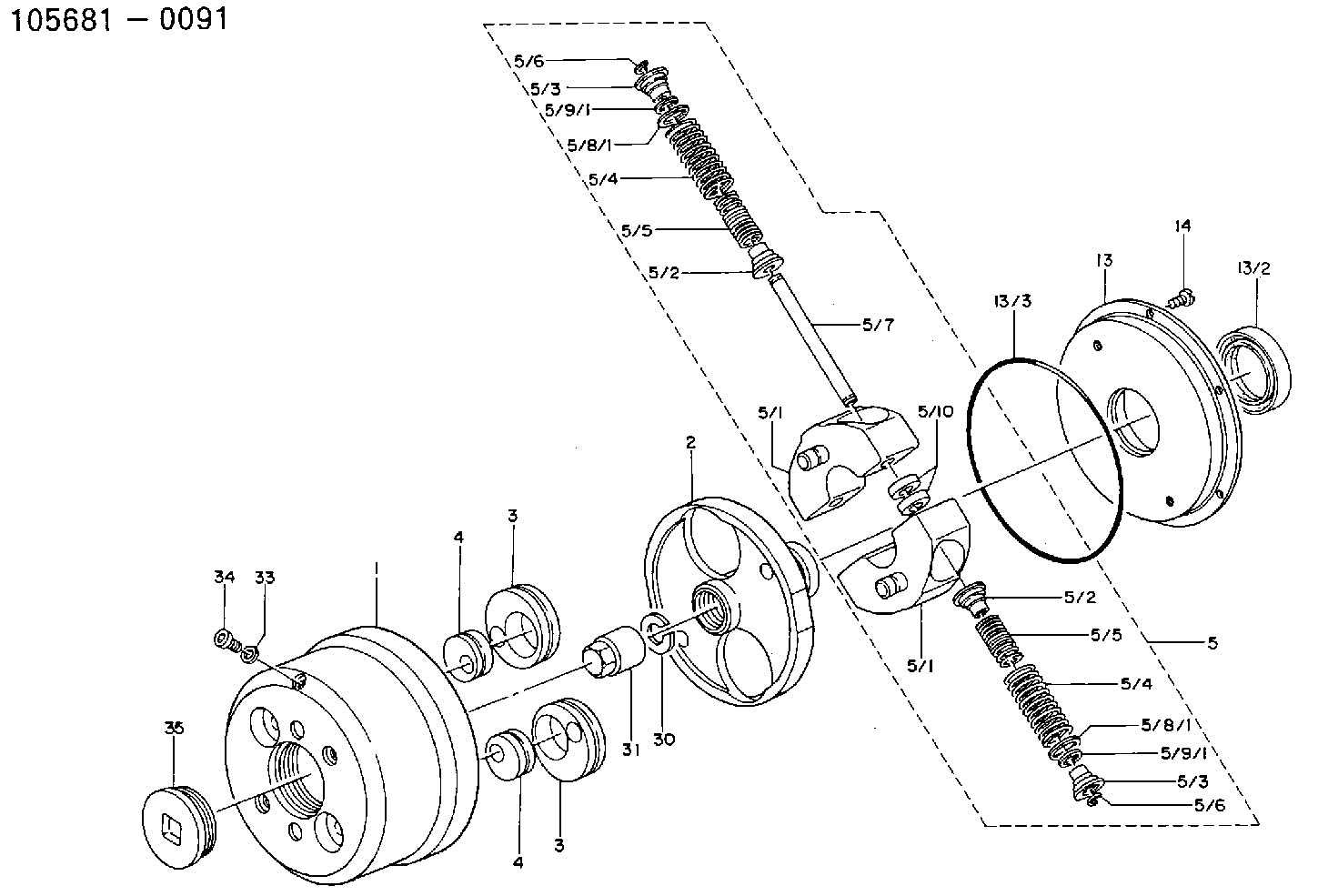
| 1. | [1] | 156800-0720 | TIMING-DEVICE HOUSING |
| 2. | [1] | 156801-1002 | FLANGE BUSHING |
| 3. | [2] | 156723-0300 | ECCENTRIC DISC |
| 3. | [2] | 156723-0300 | ECCENTRIC DISC |
| 4. | [2] | 156723-0400 | ECCENTRIC DISC |
| 4. | [2] | 156723-0400 | ECCENTRIC DISC |
| 5. | [1] | 156810-1120 | FLYWEIGHT ASSEMBLY |
| 5/1. | [2] | 156802-2320 | FLYWEIGHT |
| 5/1. | [2] | 156802-2320 | FLYWEIGHT |
| 5/2. | [4] | 156807-1100 | SLOTTED WASHER |
| 5/2. | [4] | 156807-1100 | SLOTTED WASHER |
| 5/3. | [4] | 156807-0900 | SLOTTED WASHER |
| 5/3. | [4] | 156807-0900 | SLOTTED WASHER |
| 5/4. | [4] | 156816-0400 | COMPRESSION SPRING |
| 5/4. | [4] | 156816-0400 | COMPRESSION SPRING |
| 5/5. | [4] | 156816-0500 | COMPRESSION SPRING |
| 5/5. | [4] | 156816-0500 | COMPRESSION SPRING |
| 5/6. | [4] | 156809-0300 | LOCKING WASHER |
| 5/6. | [4] | 156809-0300 | LOCKING WASHER |
| 5/7. | [2] | 156806-0900 | PIN |
| 5/8/1. | [0] | 156728-0800 | SHIM D19&15T0.1 |
| 5/8/1. | [0] | 156728-0800 | SHIM D19&15T0.1 |
| 5/8/1. | [0] | 156728-0900 | SHIM D19&15T0.3 |
| 5/8/1. | [0] | 156728-1000 | SHIM D19&15T0.5 |
| 5/8/1. | [0] | 156728-1100 | SHIM D19&15T1.0 |
| 5/8/1. | [0] | 156728-2000 | SHIM D19&15T0.4 |
| 5/8/1. | [0] | 156728-2100 | SHIM D19&15T0.7 |
| 5/9/1. | [0] | 156728-1200 | SHIM D14&10.6T0.1 |
| 5/9/1. | [0] | 156728-1200 | SHIM D14&10.6T0.1 |
| 5/9/1. | [0] | 156728-1300 | SHIM D14&10.6T0.3 |
| 5/9/1. | [0] | 156728-1400 | SHIM D14&10.6T0.5 |
| 5/9/1. | [0] | 156728-1500 | SHIM D14&10.6T1.0 |
| 5/9/1. | [0] | 156728-2200 | SHIM D14&10.6T0.4 |
| 5/9/1. | [0] | 156728-2300 | SHIM D14&10.6T0.7 |
| 5/10. | [4] | 156808-0500 | SPACER BUSHING |
| 13. | [1] | 156809-1720 | COVER |
| 13/2. | [1] | 139648-0300 | PACKING RING |
| 13/3. | [1] | 016511-3010 | O-RING |
| 14. | [6] | 012255-1040 | FLAT-HEAD SCREW M5P0.8L10 |
| 30. | [1] | 156322-0000 | LOCKING WASHER |
| 31. | [1] | 134325-0800 | UNION NUT |
| 33. | [1] | 029331-0190 | GASKET D14&10.2T1 |
| 34. | [1] | 156316-0000 | CAPSULE |
| 35. | [1] | 156314-0501 | CAP |
Include in #1:
106971-3071
as AUTOM. ADVANCE MECHANIS
Cross reference number
Zexel num
Bosch num
Firm num
Name
105681-0091
225001891A HINO
AUTOM. ADVANCE MECHANISM
* K 14KL AUTOMATIC TIMER TIMER SPG TIMER
* K 14KL AUTOMATIC TIMER TIMER SPG TIMER
Information:
Disconnect all electrical power from the panel before making a panel cutout. Make sure the area around the panel cutout is clear. Take precautions to prevent metal cuttings from entering any components that are already installed in the panel. Failure to follow these instructions may result in personal injury or damage to the panel components.
Environmental Considerations
Mount the monitor in a panel or in an enclosure in order to protect the internal circuitry.Provide adequate ventilation in the enclosure. Also, consider heat produced by other devices in the enclosure. The ambient temperature around the monitor must be maintained between 5 °C (41 °F) and 50 °C (122 °F). Make sure that you provide provisions for accessing the back panel and side panels of the monitor. Installing components and removing components requires access to the panels. The floppy disk drive is also accessed through the panels. Refer to Illustration 1.
Illustration 1 g00857541
Mounting ClearancesNote: The dimensions in Illustration 1 are only applicable if the monitor has adequate ventilation. Cooling methods must be used in order to lower air temperature within the enclosure.Mounting Hardware
Table 1
Item Description Quantity Use For
Self-locking nuts #10-32 10 (8 required) Panel or enclosure mounting In addition to the tools that are required in order to make the cut for the panel, you will need the following tools:
Drill
9.525 mm (3/8 inch) socket
15 cm (6 inch) extension rod (minimum)
Socket driver (in/lb. torque wrench recommended)
RulerPanel Mounting
In order to install the monitor in a panel, perform the following procedure:
Cut an opening in the panel by using the dimensions that are provided. Drill eight 6.4 mm (0.25 inch) holes for the mounting studs. Refer to Installation, "Dimensions" for more information.
Make sure that the sealing gasket is properly positioned on the terminal. This gasket forms a compression seal. Do not use sealing compounds.
Place the monitor in the opening in the panel. Align the studs with the mounting holes.
Install the eight self-locking nuts. Hand tighten the self-locking nuts.
Illustration 2 g00857579
Torque Sequence
Alternately tighten the self-locking nuts with the 9.525 mm (3/8 inch) socket. Tighten the nuts until the monitor is held firmly against the panel. The amount of torque that is required increases significantly as the gasket reaches the proper compression. Tighten the nuts to a torque of 2.7 N m (24 lb in). Refer to Illustration 2 for the recommended tightening sequence.Note: Tighten the nuts to a torque of 2.7 N m (24 lb in) in order to provide a proper seal and prevent damage to the monitor.