Information autom. advance mechanism
BOSCH
9 420 616 224
9420616224
ZEXEL
105676-8100
1056768100
ISUZU
8972245810
8972245810

Rating:
Scheme ###:
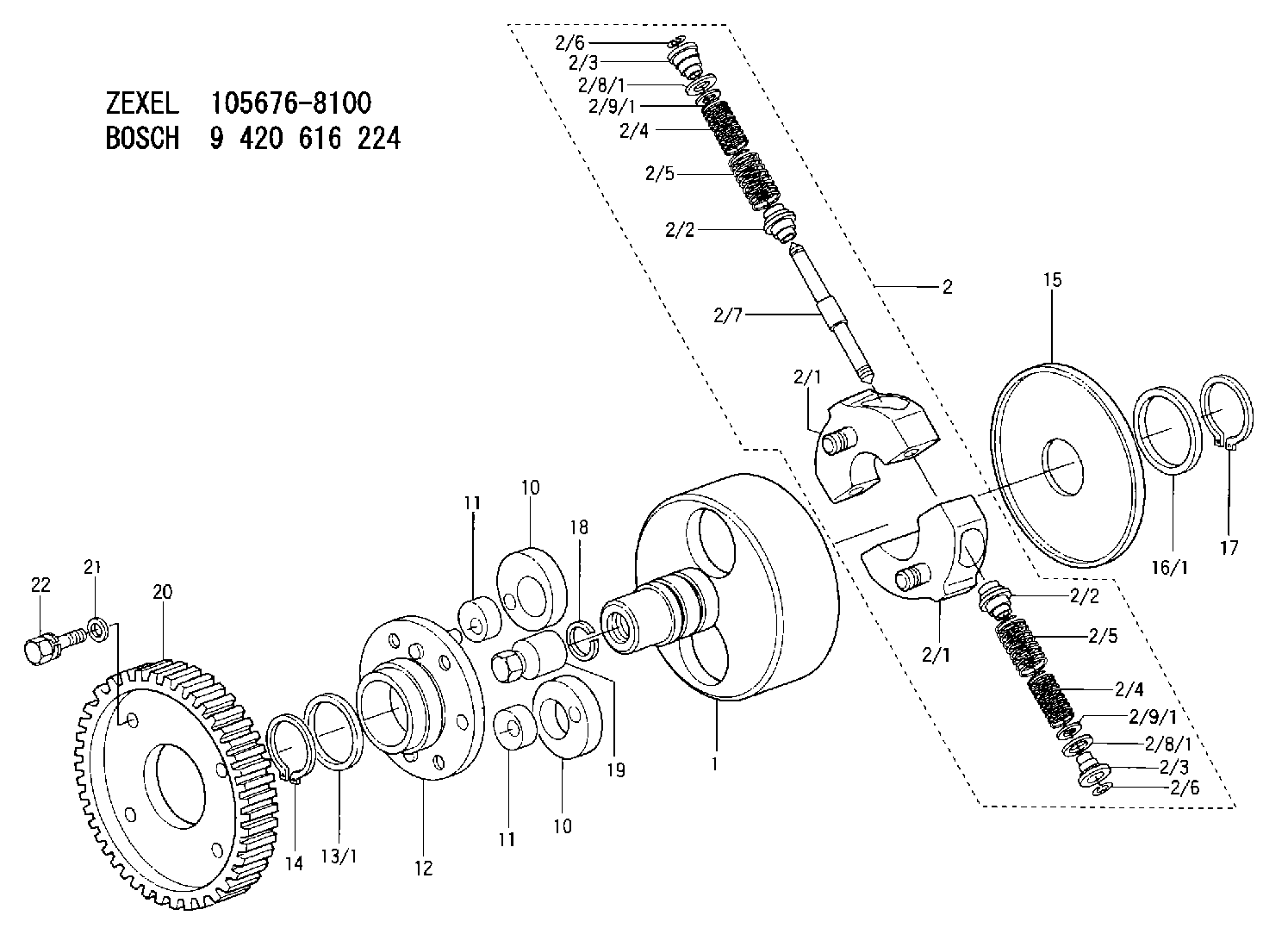
| 1. | [1] | 156739-1900 | FLANGE BUSHING |
| 2. | [1] | 156731-0820 | FLYWEIGHT ASSEMBLY |
| 2/1. | [2] | 156732-0220 | FLYWEIGHT |
| 2/1. | [2] | 156732-0220 | FLYWEIGHT |
| 2/2. | [4] | 156727-1000 | SPRING SEAT |
| 2/2. | [4] | 156727-1000 | SPRING SEAT |
| 2/3. | [4] | 156727-1000 | SPRING SEAT |
| 2/3. | [4] | 156727-1000 | SPRING SEAT |
| 2/4. | [4] | 156755-9600 | COMPRESSION SPRING |
| 2/4. | [4] | 156755-9600 | COMPRESSION SPRING |
| 2/5. | [4] | 156755-9500 | COMPRESSION SPRING |
| 2/5. | [4] | 156755-9500 | COMPRESSION SPRING |
| 2/6. | [4] | 156809-0300 | LOCKING WASHER |
| 2/6. | [4] | 156809-0300 | LOCKING WASHER |
| 2/7. | [2] | 156726-0200 | PIN |
| 2/8/1. | [0] | 156728-0800 | SHIM D19&15T0.1 |
| 2/8/1. | [0] | 156728-0900 | SHIM D19&15T0.3 |
| 2/8/1. | [0] | 156728-1000 | SHIM D19&15T0.5 |
| 2/8/1. | [0] | 156728-1100 | SHIM D19&15T1.0 |
| 2/8/1. | [0] | 156728-2000 | SHIM D19&15T0.4 |
| 2/8/1. | [0] | 156728-2000 | SHIM D19&15T0.4 |
| 2/8/1. | [0] | 156728-2100 | SHIM D19&15T0.7 |
| 2/9/1. | [0] | 156728-1200 | SHIM D14&10.6T0.1 |
| 2/9/1. | [0] | 156728-1300 | SHIM D14&10.6T0.3 |
| 2/9/1. | [0] | 156728-1400 | SHIM D14&10.6T0.5 |
| 2/9/1. | [0] | 156728-1500 | SHIM D14&10.6T1.0 |
| 2/9/1. | [0] | 156728-2200 | SHIM D14&10.6T0.4 |
| 2/9/1. | [0] | 156728-2200 | SHIM D14&10.6T0.4 |
| 2/9/1. | [0] | 156728-2300 | SHIM D14&10.6T0.7 |
| 10. | [2] | 156703-0400 | ECCENTRIC DISC |
| 10. | [2] | 156703-0400 | ECCENTRIC DISC |
| 11. | [2] | 156703-0600 | ECCENTRIC DISC |
| 11. | [2] | 156703-0600 | ECCENTRIC DISC |
| 12. | [1] | 156739-0120 | FLANGE BUSHING |
| 13/1. | [0] | 156739-0200 | SHIM D50&40.6T0.2 |
| 13/1. | [0] | 156739-0300 | SHIM D50&40.6T0.3 |
| 13/1. | [0] | 156739-0400 | SHIM D50&40.6T0.4 |
| 13/1. | [0] | 156739-0500 | SHIM D50&40.6T0.5 |
| 13/1. | [0] | 156739-0600 | SHIM D50&40.6T0.8 |
| 14. | [1] | 016020-4020 | LOCKING WASHER |
| 15. | [1] | 156739-0700 | COVER |
| 16/1. | [0] | 156739-0800 | SHIM D50&38.2T0.1 |
| 16/1. | [0] | 156739-0900 | SHIM D50&38.2T0.12 |
| 16/1. | [0] | 156739-1000 | SHIM D50&38.2T0.14 |
| 16/1. | [0] | 156739-1100 | SHIM D50&38.2T0.16 |
| 16/1. | [0] | 156739-1200 | SHIM D50&38.2T0.18 |
| 16/1. | [0] | 156739-1300 | SHIM D50&38.2T0.9 |
| 16/1. | [0] | 156739-1400 | SHIM D50&38.2T1.1 |
| 16/1. | [0] | 156739-1500 | SHIM D50&38.2T1.3 |
| 16/1. | [0] | 156739-1600 | SHIM D50&38.2T1.5 |
| 16/1. | [0] | 156739-1700 | SHIM D50&38.2T1.7 |
| 17. | [1] | 016020-3840 | LOCKING WASHER |
| 18. | [1] | 156809-0000 | LOCKING WASHER |
| 19. | [1] | 156809-0100 | UNION NUT |
| 20. | [1] | 156221-9400 | TOOTHED GEAR |
| 21. | [4] | 014010-8140 | PLAIN WASHER D18&8.5T1.6 |
| 22. | [4] | 156634-5400 | BLEEDER SCREW |
Include in #1:
101401-7530
as AUTOM. ADVANCE MECHANIS
Cross reference number
Zexel num
Bosch num
Firm num
Name
105676-8100
8972245810 ISUZU
AUTOM. ADVANCE MECHANISM
K 14KJ AUTOMATIC TIMER TIMER SCDM TIMER
K 14KJ AUTOMATIC TIMER TIMER SCDM TIMER
Information:
Illustration 1 g00596626
(1) Potentiometer (2) Light Emitting Diode (3) The Normally Closed Contact (4) Common Contact (5) Normally Open Contact
Preset the variable voltage power supply to 22 VDC.
Secure the variable voltage power supply.
Use the 4P-4029 Adjustment Tool to turn the potentiometer for the low voltage alarm module counterclockwise. Turn the potentiometer 25 times.
Remove the wire from the low voltage alarm module's positive terminal. Remove the wire from the low voltage alarm module's negative terminal.
Connect the power supply's positive lead to the low voltage alarm module's positive terminal.
Connect the power supply's negative lead to the low voltage alarm module's negative terminal.
Connect the multimeter to the N.O. contact and connect the multimeter to the COM contact. Set the multimeter to the function for measuring ohms. The multimeter should read "OL".
Energize the power supply.
Verify that the voltage is 22 VDC.
If the voltage is not 22 VDC, adjust the power supply.
Slowly turn the potentiometer for the low voltage alarm module clockwise until the LED illuminates.Note: The relay will energize after the LED illuminates. This occurs in 50 15 seconds.
Observe the multimeter in order to verify that the relay energized. The resistance reading should be low when the relay is energized.
Increase the output of the power supply to 24 VDC.Note: The LED and the relay de-energize simultaneously.
Remove the power supply's negative lead from the low voltage alarm module.
Remove the power supply's positive lead from the low voltage alarm module.
Remove the multimeter's leads from the low voltage alarm module.
Connect the system's wire to the low voltage alarm module's positive terminal. Connect the system's wire to the low voltage alarm module's negative terminal.