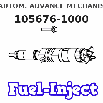
Information autom. advance mechanism
BOSCH
9 420 615 162
9420615162
ZEXEL
105676-1000
1056761000
MITSUBISHI
ME740650
me740650
Rating:
Scheme ###:
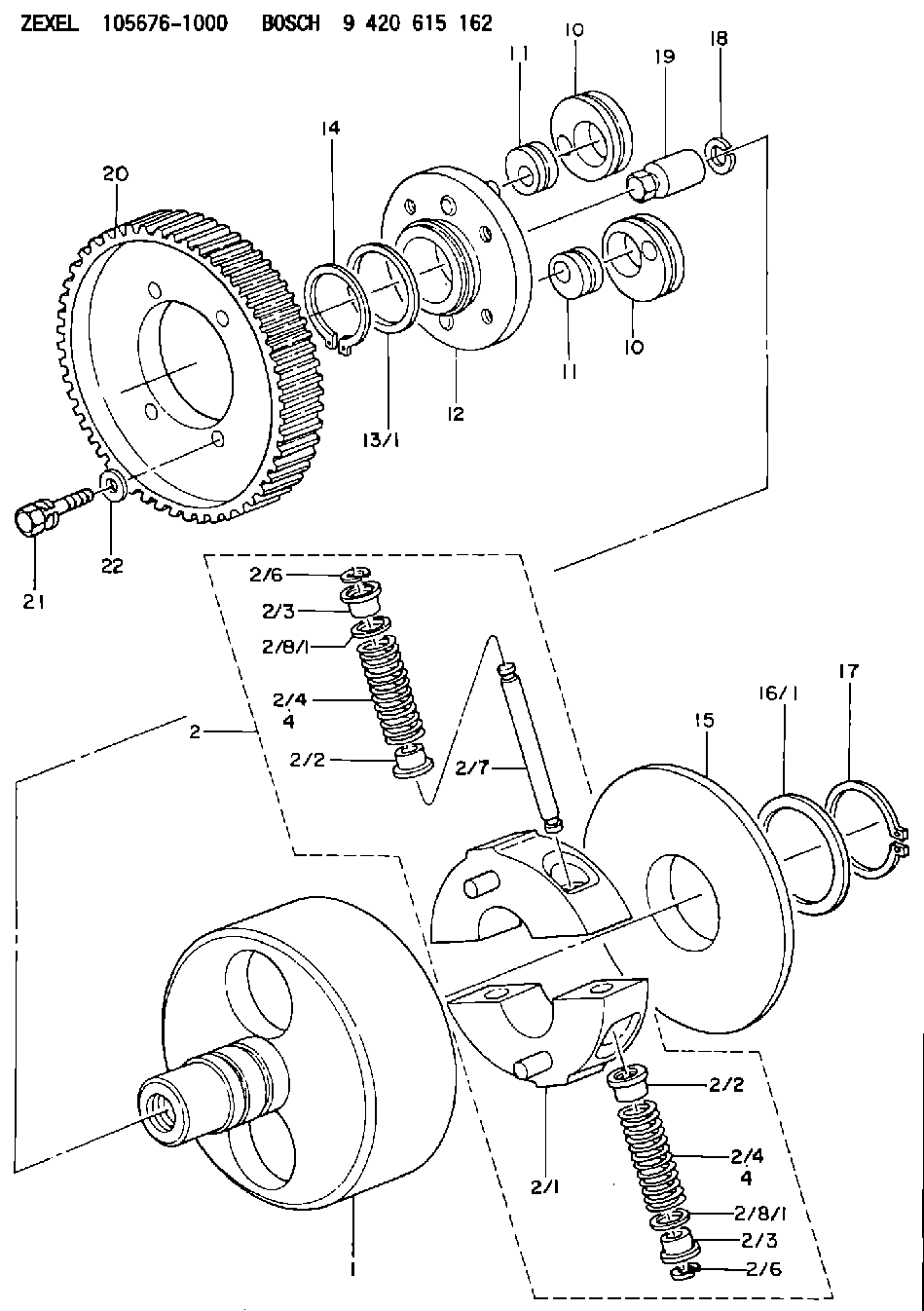
| 1. | [1] | 156700-1401 | FLANGE BUSHING |
| 2. | [1] | 156731-2720 | FLYWEIGHT ASSEMBLY |
| 2/1. | [2] | 156722-7420 | FLYWEIGHT |
| 2/2. | [4] | 156727-1000 | SPRING SEAT |
| 2/2. | [4] | 156727-1000 | SPRING SEAT |
| 2/3. | [4] | 156727-1000 | SPRING SEAT |
| 2/3. | [4] | 156727-1000 | SPRING SEAT |
| 2/4. | [4] | 156755-2000 | COMPRESSION SPRING |
| 2/4. | [4] | 156755-2000 | COMPRESSION SPRING |
| 2/6. | [4] | 156809-0300 | LOCKING WASHER |
| 2/6. | [4] | 156809-0300 | LOCKING WASHER |
| 2/7. | [2] | 156726-0200 | PIN |
| 2/8/1. | [0] | 156728-0800 | SHIM D19&15T0.1 |
| 2/8/1. | [0] | 156728-0800 | SHIM D19&15T0.1 |
| 2/8/1. | [0] | 156728-0900 | SHIM D19&15T0.3 |
| 2/8/1. | [0] | 156728-1000 | SHIM D19&15T0.5 |
| 2/8/1. | [0] | 156728-1100 | SHIM D19&15T1.0 |
| 2/8/1. | [0] | 156728-2000 | SHIM D19&15T0.4 |
| 2/8/1. | [0] | 156728-2100 | SHIM D19&15T0.7 |
| 4. | [4] | 156755-1900 | COMPRESSION SPRING |
| 4. | [4] | 156755-1900 | COMPRESSION SPRING |
| 4B. | [4] | 156756-8400 | COMPRESSION SPRING |
| 10. | [2] | 156703-0400 | ECCENTRIC DISC |
| 10. | [2] | 156703-0400 | ECCENTRIC DISC |
| 11. | [2] | 156703-0600 | ECCENTRIC DISC |
| 11. | [2] | 156703-0600 | ECCENTRIC DISC |
| 12. | [1] | 156701-0420 | FLANGE BUSHING |
| 13/1. | [0] | 156708-2200 | SHIM D46&36.1T0.1 |
| 13/1. | [0] | 156708-2300 | SHIM D46&36.1T0.12 |
| 13/1. | [0] | 156708-2400 | SHIM D46&36.1T0.14 |
| 13/1. | [0] | 156708-2500 | SHIM D46&36.1T0.16 |
| 13/1. | [0] | 156708-2600 | SHIM D46&36.1T0.18 |
| 13/1. | [0] | 156708-2700 | SHIM D46&36.1T0.9 |
| 13/1. | [0] | 156708-2800 | SHIM D46&36.1T1.10 |
| 13/1. | [0] | 156708-2900 | SHIM D46&36.1T1.3 |
| 13/1. | [0] | 156708-3000 | SHIM D46&36.1T1.5 |
| 13/1. | [0] | 156708-3100 | SHIM D46&36.1T1.7 |
| 14. | [1] | 156729-2400 | LOCKING WASHER |
| 15. | [1] | 156709-0800 | COVER |
| 16/1. | [0] | 156708-2200 | SHIM D46&36.1T0.1 |
| 16/1. | [0] | 156708-2300 | SHIM D46&36.1T0.12 |
| 16/1. | [0] | 156708-2400 | SHIM D46&36.1T0.14 |
| 16/1. | [0] | 156708-2500 | SHIM D46&36.1T0.16 |
| 16/1. | [0] | 156708-2600 | SHIM D46&36.1T0.18 |
| 16/1. | [0] | 156708-2700 | SHIM D46&36.1T0.9 |
| 16/1. | [0] | 156708-2800 | SHIM D46&36.1T1.10 |
| 16/1. | [0] | 156708-2900 | SHIM D46&36.1T1.3 |
| 16/1. | [0] | 156708-3000 | SHIM D46&36.1T1.5 |
| 16/1. | [0] | 156708-3100 | SHIM D46&36.1T1.7 |
| 17. | [1] | 156729-2400 | LOCKING WASHER |
| 18. | [1] | 029321-4060 | LOCKING WASHER |
| 19. | [1] | 131325-3100 | UNION NUT |
| 20. | [1] | 156221-5500 | TOOTHED GEAR |
| 21. | [4] | 156633-6300 | BLEEDER SCREW |
| 22. | [4] | 156615-1800 | PLAIN WASHER |
Include in #1:
101401-1681
as AUTOM. ADVANCE MECHANIS
Cross reference number
Zexel num
Bosch num
Firm num
Name
105676-1000
ME740650 MITSUBISHI
AUTOM. ADVANCE MECHANISM
K 14KJ AUTOMATIC TIMER TIMER SCDM TIMER
K 14KJ AUTOMATIC TIMER TIMER SCDM TIMER
105676-1000
ME740605 MITSUBISHI
AUTOM. ADVANCE MECHANISM
A K 14KJ AUTOMATIC TIMER TIMER SCDM TIMER
A K 14KJ AUTOMATIC TIMER TIMER SCDM TIMER
Information:
To avoid possible engine damage or another immediate shutdown, the water temperature fault must be corrected before attempting to restart the engine.
Even though the starter motor circuit can now be engaged, there is no fuel flow to the engine. The fuel flow to the engine is stopped until the coolant temperature falls below the rating for the water temperature contactor switch (WTS). When the coolant temperature falls below the rating for the water temperature contactor switch (WTS), the contactor switch opens again. The fuel shutoff solenoid is de-energized when the switch reopens. This allows fuel flow to the engine. The engine can then be restarted.2301A Electric Governor Control
The 2301A Electric Governor Control activates all of the components that are in the electric protection system. The components are activated in the same manner when the nonelectric governor is used. One difference exists in the main circuit. The fuel shutoff solenoid (FSOS) (line 43) is not used.When the electric governor control is used, the engine must run in a normal condition in order for the electric circuit to operate in the manner that is described below.
Current flows from the terminals (TS-28) (line 43) and (TS-31) (line 44), which are located on the terminal strip in the junction box.
Current from terminals (TS-28) (line 43) and (TS-31) (line 44) flows through the preregulator (PR) (line 48) or the fuse (F4) to the electric governor control.
When the engine flywheel is rotating, the current also flows through the electric governor actuator (EGA) (line 52). When a fault in the system causes the current to energize the slave relay (SR1), the following events occur in the electric circuit in order to stop the engine.
The slave relay (SR1) opens across the contacts (SR1-30) and (SR1-87a) (line 45). The relay closes across the contacts (SR1-30) and (SR1-87) (line 43).
When the circuit opens across contacts (SR1-30) and (SR1-87a), the current is stopped to the electric governor control.
Current to the electric governor actuator (EGA) is also stopped.
The mechanical spring load in the electric governor actuator (EGA) will now move the fuel control rod in order to stop fuel flow to the engine.Note: With the exception of the differences that are described in this section of the manual, all of the fault circuits in the electric protection system are identical for the 2301A Electric Governor Control and for the nonelectric governor control.
Illustration 3 g00292518
Junction Box Wiring for ETS with OP, WT,