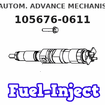
Information autom. advance mechanism
BOSCH
9 420 615 563
9420615563
ZEXEL
105676-0611
1056760611
Rating:
Scheme ###:
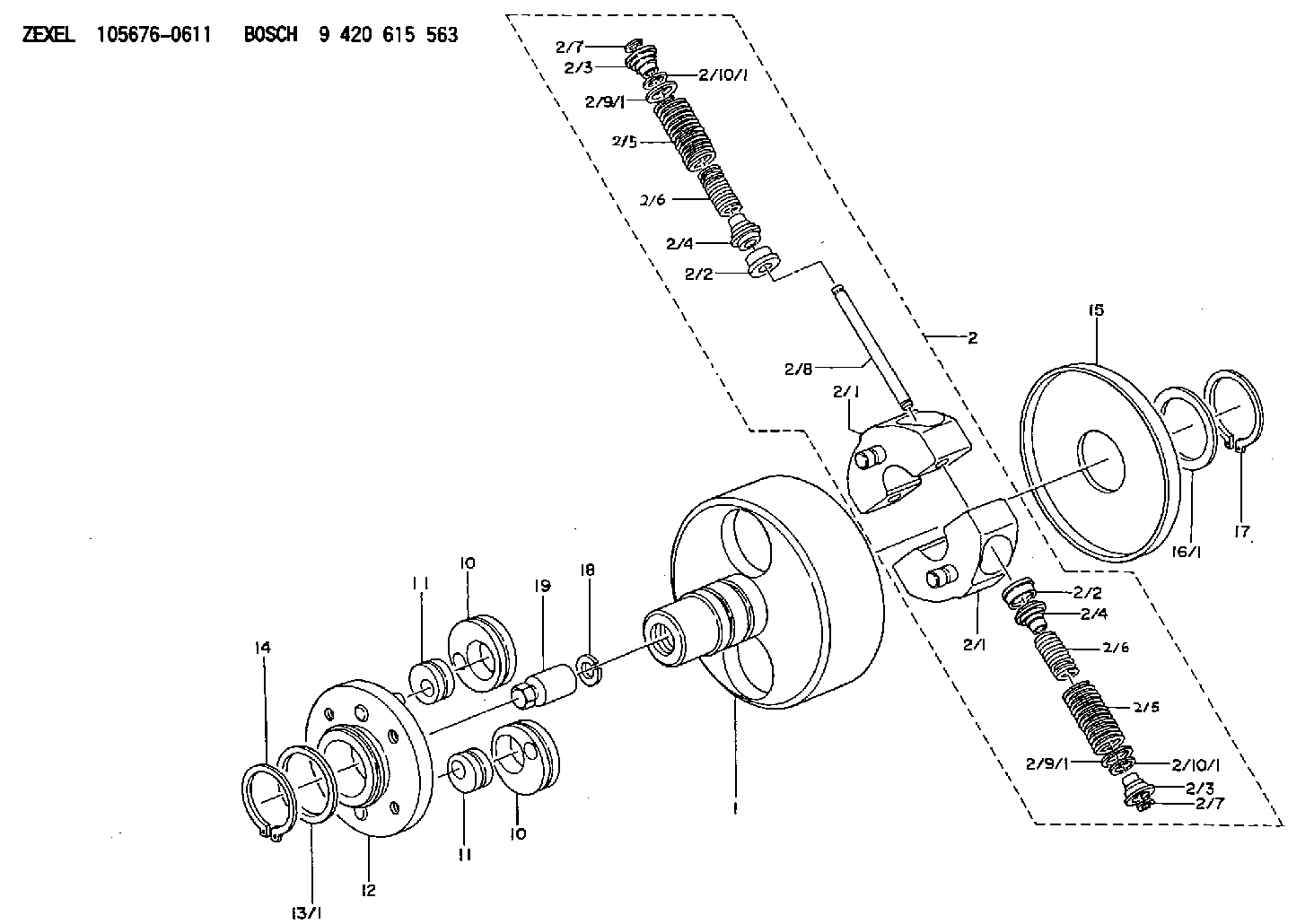
| 1. | [1] | 156700-0800 | FLANGE BUSHING |
| 2. | [1] | 156730-6120 | FLYWEIGHT ASSEMBLY |
| 2/1. | [2] | 156722-8120 | FLYWEIGHT |
| 2/1. | [2] | 156722-8120 | FLYWEIGHT |
| 2/2. | [4] | 156807-1200 | SLOTTED WASHER |
| 2/2. | [4] | 156807-1200 | SLOTTED WASHER |
| 2/3. | [4] | 156807-1300 | SLOTTED WASHER |
| 2/3. | [4] | 156807-1300 | SLOTTED WASHER |
| 2/4. | [4] | 156727-0900 | SLOTTED WASHER |
| 2/4. | [4] | 156727-0900 | SLOTTED WASHER |
| 2/5. | [4] | 156725-2400 | COMPRESSION SPRING |
| 2/5. | [4] | 156725-2400 | COMPRESSION SPRING |
| 2/6. | [4] | 156725-2500 | COMPRESSION SPRING |
| 2/6. | [4] | 156725-2500 | COMPRESSION SPRING |
| 2/7. | [4] | 156729-0500 | LOCKING WASHER |
| 2/7. | [4] | 156729-0500 | LOCKING WASHER |
| 2/8. | [2] | 156726-0600 | PIN |
| 2/9/1. | [0] | 156728-0800 | SHIM D19&15T0.1 |
| 2/9/1. | [0] | 156728-0900 | SHIM D19&15T0.3 |
| 2/9/1. | [0] | 156728-1000 | SHIM D19&15T0.5 |
| 2/9/1. | [0] | 156728-1100 | SHIM D19&15T1.0 |
| 2/9/1. | [0] | 156728-2000 | SHIM D19&15T0.4 |
| 2/9/1. | [0] | 156728-2000 | SHIM D19&15T0.4 |
| 2/9/1. | [0] | 156728-2100 | SHIM D19&15T0.7 |
| 2/10/1. | [0] | 156728-1200 | SHIM D14&10.6T0.1 |
| 2/10/1. | [0] | 156728-1300 | SHIM D14&10.6T0.3 |
| 2/10/1. | [0] | 156728-1400 | SHIM D14&10.6T0.5 |
| 2/10/1. | [0] | 156728-1500 | SHIM D14&10.6T1.0 |
| 2/10/1. | [0] | 156728-2200 | SHIM D14&10.6T0.4 |
| 2/10/1. | [0] | 156728-2300 | SHIM D14&10.6T0.7 |
| 2/10/1. | [0] | 156728-2300 | SHIM D14&10.6T0.7 |
| 10. | [2] | 156703-0400 | ECCENTRIC DISC |
| 10. | [2] | 156703-0400 | ECCENTRIC DISC |
| 11. | [2] | 156703-0600 | ECCENTRIC DISC |
| 11. | [2] | 156703-0600 | ECCENTRIC DISC |
| 12. | [1] | 156701-0420 | FLANGE BUSHING |
| 13/1. | [0] | 156708-2200 | SHIM D46&36.1T0.1 |
| 13/1. | [0] | 156708-2300 | SHIM D46&36.1T0.12 |
| 13/1. | [0] | 156708-2400 | SHIM D46&36.1T0.14 |
| 13/1. | [0] | 156708-2500 | SHIM D46&36.1T0.16 |
| 13/1. | [0] | 156708-2600 | SHIM D46&36.1T0.18 |
| 13/1. | [0] | 156708-2700 | SHIM D46&36.1T0.9 |
| 13/1. | [0] | 156708-2800 | SHIM D46&36.1T1.10 |
| 13/1. | [0] | 156708-2900 | SHIM D46&36.1T1.3 |
| 13/1. | [0] | 156708-3000 | SHIM D46&36.1T1.5 |
| 13/1. | [0] | 156708-3100 | SHIM D46&36.1T1.7 |
| 14. | [1] | 016020-3610 | LOCKING WASHER |
| 15. | [1] | 156709-0800 | COVER |
| 16/1. | [0] | 156708-2200 | SHIM D46&36.1T0.1 |
| 16/1. | [0] | 156708-2300 | SHIM D46&36.1T0.12 |
| 16/1. | [0] | 156708-2400 | SHIM D46&36.1T0.14 |
| 16/1. | [0] | 156708-2500 | SHIM D46&36.1T0.16 |
| 16/1. | [0] | 156708-2600 | SHIM D46&36.1T0.18 |
| 16/1. | [0] | 156708-2700 | SHIM D46&36.1T0.9 |
| 16/1. | [0] | 156708-2800 | SHIM D46&36.1T1.10 |
| 16/1. | [0] | 156708-2900 | SHIM D46&36.1T1.3 |
| 16/1. | [0] | 156708-3000 | SHIM D46&36.1T1.5 |
| 16/1. | [0] | 156708-3100 | SHIM D46&36.1T1.7 |
| 17. | [1] | 016020-3610 | LOCKING WASHER |
| 18. | [1] | 029321-4060 | LOCKING WASHER |
| 19. | [1] | 131325-3100 | UNION NUT |
Include in #1:
101601-5466
as AUTOM. ADVANCE MECHANIS
Cross reference number
Zexel num
Bosch num
Firm num
Name
9 420 615 563
225003180A HINO
AUTOM. ADVANCE MECHANISM
A * K 14KJ TIMER SCDM TIMER
A * K 14KJ TIMER SCDM TIMER
Information:
Image1.1.1
Image1.1.2
Image1.1.3
Image1.1.4
Image1.1.5
Image1.1.6
Image1.1.7
Image1.1.8
Image1.1.9
PROCEDURES FOR DPF MODULE REWORK
PROCEDURE ( A ) See Image 1.2.1
Butt weld ring flush to retainer ring on the inlet assembly in 4 spots.
Fillet weld (3 mm weld size) 4 tabs (at 0, 90,180 and 270 degrees.
PROCEDURE ( B ) See Image 1.2.2
Butt weld ring flush to retainer ring on the inlet assembly in 4 spots.
Fillet weld (3 mm weld size) 4 tabs (at 0, 90,180 and 270 degrees.
PROCEDURE ( C ) See Image 1.2.3
Butt weld ring flush to retainer ring on the inlet assembly in 4 spots.
Fillet weld (3 mm weld size) 4 tabs (at 0, 90,180 and 270 degrees.
PROCEDURE ( D ) See Image 1.2.4
Butt weld ring flush to retainer ring on the inlet assembly in 4 spots.
Fillet weld (3 mm weld size) 4 tabs (at 0, 90,180 and 270 degrees.
PROCEDURE ( E ) See Image 1.2.5
Butt weld ring flush to retainer ring on inlet assembly in 4 spots.
Fillet weld 2 pins (at 0 and 180 degree orientation) to outlet side of DPF's 300 mm from each other.
Drill 5/8" holes in the outlet assembly flanges 300 mm from each other.
Place tube flush to the flange inside this hole and weld to outlet assembly.
PROCEDURE ( F ) See Image 1.2.6
Position plates (at 0 and 180 degree orientation) to outlet side of the DPF flange.
Allow plates to extend ( minimum 1/4 inch ) past outer edge. Using slots in plates
weld into place.
PROCEDURE ( G ) See Image 1.2.7
Fillet weld (3 mm weld size) 2 pins (at 0 and 180 degree orientation) to outlet side of DPF 260 mm from each other.
Drill a 5/8" hole in the outlet assembly flange 260 mm from each other 13 mm deep.
Place tube flush to the flange inside this hole and weld to outlet assembly.
PROCEDURE ( H ) See Image 1.2.8
Fillet weld 2 pins (at 0 and 180 degree orientation) to outlet side of both DPF's 300 mm from each other.
Drill 5/8" holes in the outlet assembly flanges 300 mm from each other 13 mm deep.
Place tubes flush to the flange inside this hole and weld to outlet assembly.
PROCEDURE ( I ) See Image 1.2.9 and Image 1.2.10
Remove the clamp and gasket from DPF inlet side.
Mate inlet flange to DPF without gasket or clamp.
Tack weld in place.
Apply a continuous weld to the inlet flange/DPF seam.
Image1.2.1
Image1.2.2
Image1.2.3
Image1.2.4
Image1.2.5
Image1.2.6
Image1.2.7
Image1.2.8
Image1.2.9
Image1.2.10
Filter Module Cross Reference Guide See Image 1.3.1.
Image1.3.1