Information autom. advance mechanism
BOSCH
9 420 617 204
9420617204
ZEXEL
105676-0161
1056760161
Rating:
Scheme ###:
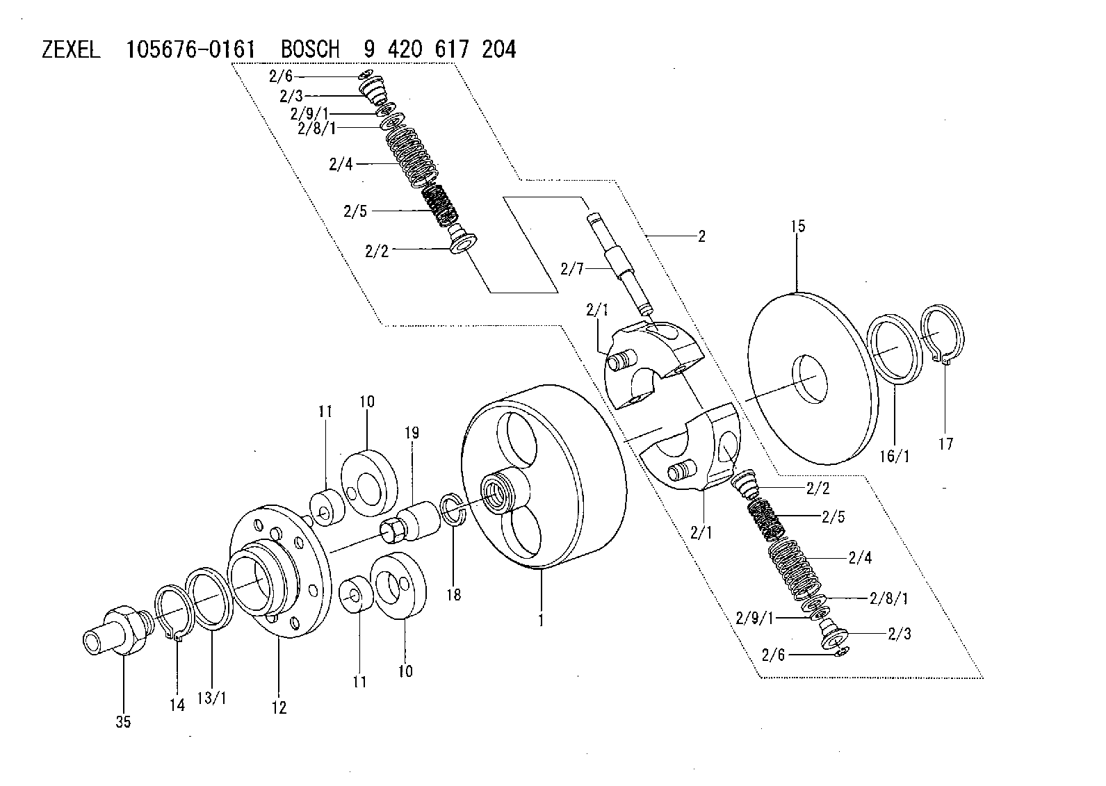
| 1. | [1] | 156700-0700 | FLANGE BUSHING |
| 2. | [1] | 156730-0920 | FLYWEIGHT ASSEMBLY |
| 2/1. | [2] | 156722-9420 | FLYWEIGHT |
| 2/1. | [2] | 156722-9420 | FLYWEIGHT |
| 2/2. | [4] | 156727-1000 | SPRING SEAT |
| 2/2. | [4] | 156727-1000 | SPRING SEAT |
| 2/3. | [4] | 156727-1000 | SPRING SEAT |
| 2/3. | [4] | 156727-1000 | SPRING SEAT |
| 2/4. | [4] | 156724-2800 | COMPRESSION SPRING |
| 2/4. | [4] | 156724-2800 | COMPRESSION SPRING |
| 2/5. | [4] | 156724-2900 | COMPRESSION SPRING |
| 2/5. | [4] | 156724-2900 | COMPRESSION SPRING |
| 2/6. | [4] | 156809-0300 | LOCKING WASHER |
| 2/6. | [4] | 156809-0300 | LOCKING WASHER |
| 2/7. | [2] | 156726-0200 | PIN |
| 2/8/1. | [0] | 156728-0800 | SHIM D19&15T0.1 |
| 2/8/1. | [0] | 156728-0900 | SHIM D19&15T0.3 |
| 2/8/1. | [0] | 156728-1000 | SHIM D19&15T0.5 |
| 2/8/1. | [0] | 156728-1100 | SHIM D19&15T1.0 |
| 2/8/1. | [0] | 156728-2000 | SHIM D19&15T0.4 |
| 2/8/1. | [0] | 156728-2100 | SHIM D19&15T0.7 |
| 2/8/1. | [0] | 156728-2400 | SHIM D19&15T0.6 |
| 2/8/1. | [0] | 156728-2500 | SHIM D19&15T0.8 |
| 2/8/1. | [0] | 156728-2600 | SHIM D19&15T0.9 |
| 2/8/1. | [0] | 156728-2600 | SHIM D19&15T0.9 |
| 2/9/1. | [0] | 156728-1200 | SHIM D14&10.6T0.1 |
| 2/9/1. | [0] | 156728-1300 | SHIM D14&10.6T0.3 |
| 2/9/1. | [0] | 156728-1400 | SHIM D14&10.6T0.5 |
| 2/9/1. | [0] | 156728-1500 | SHIM D14&10.6T1.0 |
| 2/9/1. | [0] | 156728-2200 | SHIM D14&10.6T0.4 |
| 2/9/1. | [0] | 156728-2200 | SHIM D14&10.6T0.4 |
| 2/9/1. | [0] | 156728-2300 | SHIM D14&10.6T0.7 |
| 2/9/1. | [0] | 156728-2700 | SHIM D14&10.6T0.6 |
| 2/9/1. | [0] | 156728-2800 | SHIM D14&10.6T0.8 |
| 2/9/1. | [0] | 156728-2900 | SHIM D14&10.6T0.9 |
| 10. | [2] | 156703-0500 | ECCENTRIC DISC |
| 10. | [2] | 156703-0500 | ECCENTRIC DISC |
| 11. | [2] | 156703-0600 | ECCENTRIC DISC |
| 11. | [2] | 156703-0600 | ECCENTRIC DISC |
| 12. | [1] | 156701-0820 | FLANGE BUSHING |
| 13/1. | [0] | 156708-2200 | SHIM D46&36.1T0.1 |
| 13/1. | [0] | 156708-2300 | SHIM D46&36.1T0.12 |
| 13/1. | [0] | 156708-2400 | SHIM D46&36.1T0.14 |
| 13/1. | [0] | 156708-2500 | SHIM D46&36.1T0.16 |
| 13/1. | [0] | 156708-2600 | SHIM D46&36.1T0.18 |
| 13/1. | [0] | 156708-2700 | SHIM D46&36.1T0.9 |
| 13/1. | [0] | 156708-2800 | SHIM D46&36.1T1.10 |
| 13/1. | [0] | 156708-2900 | SHIM D46&36.1T1.3 |
| 13/1. | [0] | 156708-3000 | SHIM D46&36.1T1.5 |
| 13/1. | [0] | 156708-3100 | SHIM D46&36.1T1.7 |
| 14. | [1] | 156729-2400 | LOCKING WASHER |
| 15. | [1] | 156709-0800 | COVER |
| 16/1. | [0] | 156708-2200 | SHIM D46&36.1T0.1 |
| 16/1. | [0] | 156708-2300 | SHIM D46&36.1T0.12 |
| 16/1. | [0] | 156708-2400 | SHIM D46&36.1T0.14 |
| 16/1. | [0] | 156708-2500 | SHIM D46&36.1T0.16 |
| 16/1. | [0] | 156708-2600 | SHIM D46&36.1T0.18 |
| 16/1. | [0] | 156708-2700 | SHIM D46&36.1T0.9 |
| 16/1. | [0] | 156708-2800 | SHIM D46&36.1T1.10 |
| 16/1. | [0] | 156708-2900 | SHIM D46&36.1T1.3 |
| 16/1. | [0] | 156708-3000 | SHIM D46&36.1T1.5 |
| 16/1. | [0] | 156708-3100 | SHIM D46&36.1T1.7 |
| 17. | [1] | 156729-2400 | LOCKING WASHER |
| 18. | [1] | 029321-4060 | LOCKING WASHER |
| 19. | [1] | 131325-3100 | UNION NUT |
| 35. | [1] | 156709-0900 | ADAPTOR |
Include in #1:
101401-2015
as AUTOM. ADVANCE MECHANIS
Cross reference number
Zexel num
Bosch num
Firm num
Name
105676-0161
9 420 617 204
AUTOM. ADVANCE MECHANISM
* K
* K
Information:
Start By:a. remove rocker arm assemblies and push rods1. Disconnect the governor control linkage. See the 3114 & 3116 Engines Governor Service Manual, Form No. SENR6454.
Do not move the fuel control linkage or the injector racks with out the Injector Compressors [Tool (A)] installed. Damage to the fuel injectors can result. After installation of Tool (A), tap on the top of each fuel injector lightly with a rubber mallet to prevent any binding or side loading in the fuel injectors.
2. When removing the fuel control linkage with the fuel injectors in place, install Tool (A) on the fuel injectors, and slightly compress the injector springs.3. Remove four bolts (1) and fuel control linkage (2). The following steps are for the installation of the fuel control linkage.4. Be sure the two screws in each inboard bracket are loose.5. Put fuel control linkage in position on the cylinder head assembly. Be sure all injector racks are engaged and the small dowel in each mounting bracket is in the proper position before tightening bolts (1). Install four bolts (1), and tighten them as follows: a. Tighten the two outer bearing bracket mounting bolts.b. Tighten the inner bearing bracket(s) mounting bolt(s).c. Position the inner bearing(s) to allow free rotation of the rack control rod.d. Tighten the two screws in on each inner bracket(s) to a torque of 3.5 0.2 N m (31 2 lb in).e. The control rod must rotate when a force of 4.4 N (1 lb) or less is applied to control lever (3) in the direction indicated by arrows.6. Connect the governor control linkage. See the 3114 & 3116 Engines Governor Service Manual, Form No. SENR6454.7. After installation of the rocker arm assemblies and push rods, Check and/or adjust the following: Injector Synchronization, Fuel Setting, Fuel Timing, Valve Lash. See the 3114 & 3116 Diesel Truck Engines Systems Operation Testing & Adjusting module, Form No. SENR6437 to check and/or adjust the above items.End By:a. install rocker arm assemblies and push rods
Have questions with 105676-0161?
Group cross 105676-0161 ZEXEL
Hino
Hino
Hino
105676-0161
9 420 617 204
AUTOM. ADVANCE MECHANISM