Information autom. advance mechanism
BOSCH
9 420 616 440
9420616440
ZEXEL
105676-0060
1056760060
HINO
225001840A
225001840a

Rating:
Scheme ###:
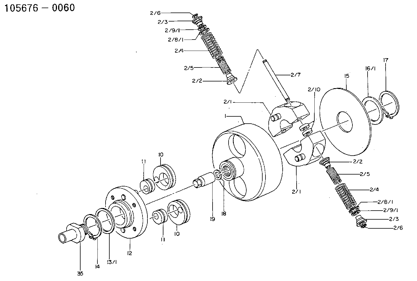
| 1. | [1] | 156700-0500 | FLANGE BUSHING |
| 2. | [1] | 156730-0120 | FLYWEIGHT ASSEMBLY |
| 2/1. | [2] | 156722-9821 | FLYWEIGHT |
| 2/1. | [2] | 156722-9821 | FLYWEIGHT |
| 2/2. | [4] | 156727-1000 | SPRING SEAT |
| 2/2. | [4] | 156727-1000 | SPRING SEAT |
| 2/3. | [4] | 156727-1000 | SPRING SEAT |
| 2/3. | [4] | 156727-1000 | SPRING SEAT |
| 2/4. | [4] | 156704-1600 | COMPRESSION SPRING |
| 2/4. | [4] | 156704-1600 | COMPRESSION SPRING |
| 2/5. | [4] | 156704-1800 | COMPRESSION SPRING |
| 2/5. | [4] | 156704-1800 | COMPRESSION SPRING |
| 2/6. | [4] | 156809-0300 | LOCKING WASHER |
| 2/6. | [4] | 156809-0300 | LOCKING WASHER |
| 2/7. | [2] | 156726-1000 | PIN |
| 2/8/1. | [0] | 156728-0800 | SHIM D19&15T0.1 |
| 2/8/1. | [0] | 156728-0800 | SHIM D19&15T0.1 |
| 2/8/1. | [0] | 156728-0900 | SHIM D19&15T0.3 |
| 2/8/1. | [0] | 156728-1000 | SHIM D19&15T0.5 |
| 2/8/1. | [0] | 156728-1100 | SHIM D19&15T1.0 |
| 2/8/1. | [0] | 156728-2000 | SHIM D19&15T0.4 |
| 2/8/1. | [0] | 156728-2100 | SHIM D19&15T0.7 |
| 2/9/1. | [0] | 156728-1200 | SHIM D14&10.6T0.1 |
| 2/9/1. | [0] | 156728-1200 | SHIM D14&10.6T0.1 |
| 2/9/1. | [0] | 156728-1300 | SHIM D14&10.6T0.3 |
| 2/9/1. | [0] | 156728-1400 | SHIM D14&10.6T0.5 |
| 2/9/1. | [0] | 156728-1500 | SHIM D14&10.6T1.0 |
| 2/9/1. | [0] | 156728-2200 | SHIM D14&10.6T0.4 |
| 2/9/1. | [0] | 156728-2300 | SHIM D14&10.6T0.7 |
| 2/10. | [2] | 156808-0800 | SPACER BUSHING |
| 10. | [2] | 156723-0700 | ECCENTRIC DISC |
| 10. | [2] | 156723-0700 | ECCENTRIC DISC |
| 11. | [2] | 156723-0400 | ECCENTRIC DISC |
| 11. | [2] | 156723-0400 | ECCENTRIC DISC |
| 12. | [1] | 156701-0320 | FLANGE BUSHING |
| 13/1. | [0] | 156708-2200 | SHIM D46&36.1T0.1 |
| 13/1. | [0] | 156708-2300 | SHIM D46&36.1T0.12 |
| 13/1. | [0] | 156708-2400 | SHIM D46&36.1T0.14 |
| 13/1. | [0] | 156708-2500 | SHIM D46&36.1T0.16 |
| 13/1. | [0] | 156708-2600 | SHIM D46&36.1T0.18 |
| 13/1. | [0] | 156708-2700 | SHIM D46&36.1T0.9 |
| 13/1. | [0] | 156708-2800 | SHIM D46&36.1T1.10 |
| 13/1. | [0] | 156708-2900 | SHIM D46&36.1T1.3 |
| 13/1. | [0] | 156708-3000 | SHIM D46&36.1T1.5 |
| 13/1. | [0] | 156708-3100 | SHIM D46&36.1T1.7 |
| 14. | [1] | 016020-3620 | LOCKING WASHER |
| 15. | [1] | 156709-0600 | PLATE |
| 16/1. | [0] | 156708-2200 | SHIM D46&36.1T0.1 |
| 16/1. | [0] | 156708-2300 | SHIM D46&36.1T0.12 |
| 16/1. | [0] | 156708-2400 | SHIM D46&36.1T0.14 |
| 16/1. | [0] | 156708-2500 | SHIM D46&36.1T0.16 |
| 16/1. | [0] | 156708-2600 | SHIM D46&36.1T0.18 |
| 16/1. | [0] | 156708-2700 | SHIM D46&36.1T0.9 |
| 16/1. | [0] | 156708-2800 | SHIM D46&36.1T1.10 |
| 16/1. | [0] | 156708-2900 | SHIM D46&36.1T1.3 |
| 16/1. | [0] | 156708-3000 | SHIM D46&36.1T1.5 |
| 16/1. | [0] | 156708-3100 | SHIM D46&36.1T1.7 |
| 17. | [1] | 016020-3620 | LOCKING WASHER |
| 18. | [1] | 029321-4060 | LOCKING WASHER |
| 19. | [1] | 131325-3100 | UNION NUT |
| 35. | [1] | 156709-0900 | ADAPTOR |
Include in #1:
101601-2781
as AUTOM. ADVANCE MECHANIS
Cross reference number
Zexel num
Bosch num
Firm num
Name
105676-0060
225001840A HINO
AUTOM. ADVANCE MECHANISM
K 14KJ AUTOMATIC TIMER TIMER SCDM TIMER
K 14KJ AUTOMATIC TIMER TIMER SCDM TIMER
105676-0060
225001841A HINO
AUTOM. ADVANCE MECHANISM
A K 14KJ AUTOMATIC TIMER TIMER SCDM TIMER
A K 14KJ AUTOMATIC TIMER TIMER SCDM TIMER
Information:
At operating temperature, the engine coolant is hot and under pressure. Steam can cause personal injury. Check the coolant level only after the engine has been stopped and the fill cap is cool enough to touch with your bare hand. Remove the fill cap slowly to relieve pressure in the cooling system. Cooling system conditioner contains alkali. Avoid contact with skin and eyes to prevent personal injury.
1. Drain the coolant from the cooling system into a suitable container for storage or disposal. 2. Loosen bolts (1) and (2) on water pump drive (3).3. Remove V-belt (4) from the drive pulley on the water pump and the pulley on the water pump drive.4. Remove two hose clamps (5). Disconnect the hose used between the water pump and the water temperature regulator housing at the water pump.5. Remove four bolts (6) that hold the water pump to the front of the engine. Carefully remove the water pump and two O-ring seals from the front of the engine. The following steps are for the installation of the water pump.6. Check the condition of the two O-ring seals used between the water pump and the cylinder block. If the seals are damaged, use new parts for replacement.7. Install the two O-ring seals in the cover of the water pump. Put the water pump in position on the front of the engine, and install four bolts (6) that hold it.8. Connect the short hose used between the water pump and the water temperature regulator housing to the water pump. Install two clamps (5) that hold the hose in position.9. Put V-belt (4) in position on the water pump drive pulley and the pulley on water pump drive.10. Adjust the tension of water pump drive V-belt (4). Bolt (7) or square hole (8) are used to apply and hold V-belt tension. See the topic "Alternator And Fan Drive Belts, Inspect/Adjust/Replace" in the 3114 & 3116 ATAAC Diesel Truck Engine Operation & Maintenance Manual, Form No. SEBU6723. Also, refer to the "Belt Tension Chart" in the 3114 & 3116 Diesel Truck Engines Specifications module, Form No. SENR6436.11. Fill the cooling system with coolant to the correct level. See the topic "Cooling System" in the 3114 & 3116 ATAAC Diesel Truck Engine Operation & Maintenance Manual, Form No. SEBU6723.Disassemble & Assemble Water Pump
Start By:a. remove water pump 1. Remove two O-ring seals (1) from the rear cover of the water pump. Remove four bolts (2) and the washers. Remove the rear cover and gasket. 2. Put the water pump in a press. Use spacer plates to level the water pump as shown.3. Using a suitable size drive plate from Tool (A) and a press, push the