Information autom. advance mechanism
BOSCH
9 420 615 129
9420615129
ZEXEL
105671-0530
1056710530

Rating:
Scheme ###:
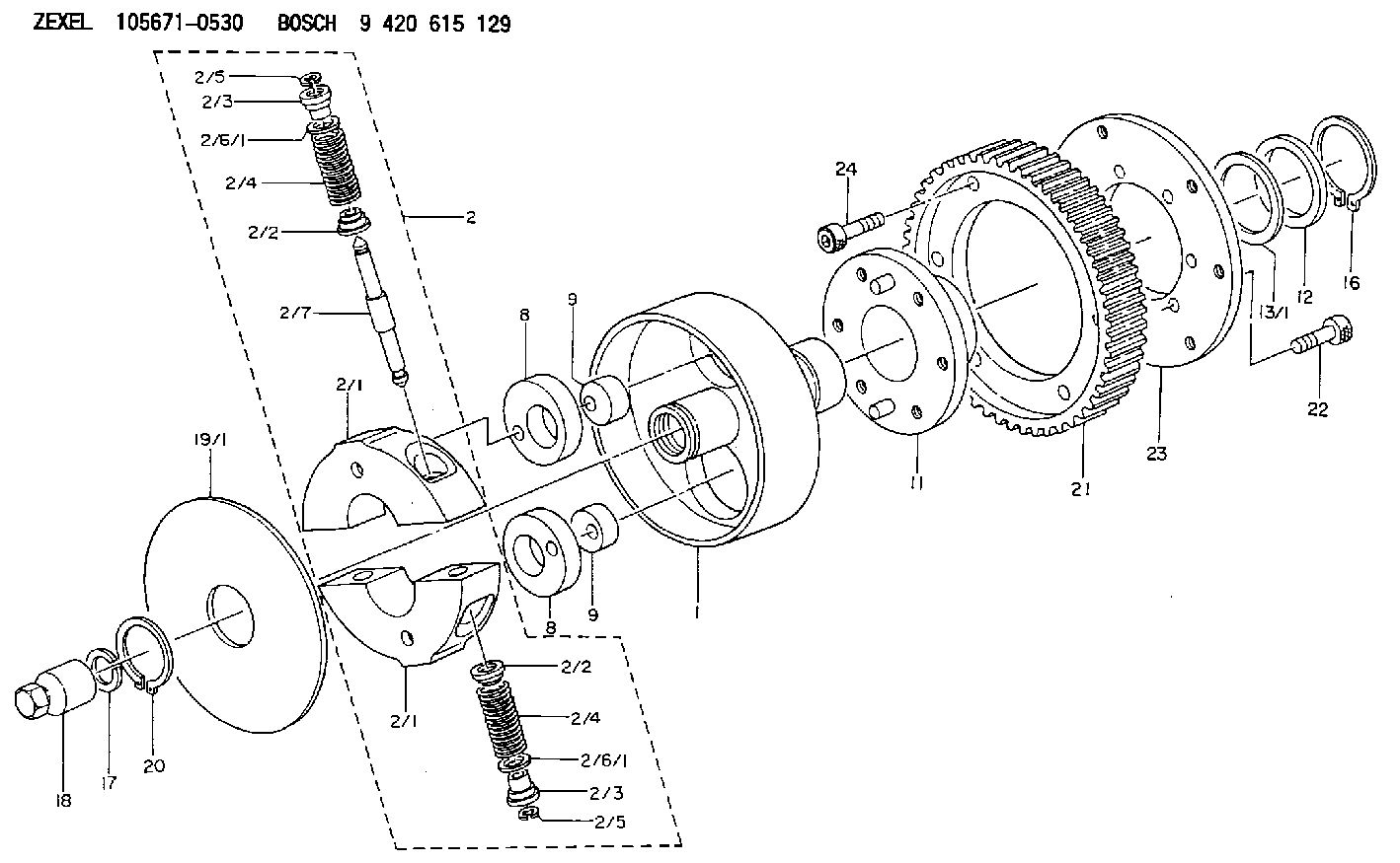
| 1. | [1] | 156700-1000 | FLANGE BUSHING |
| 2. | [1] | 156718-3620 | FLYWEIGHT ASSEMBLY |
| 2/1. | [2] | 156702-8520 | FLYWEIGHT |
| 2/1. | [2] | 156702-8520 | FLYWEIGHT |
| 2/2. | [4] | 156707-0100 | SLOTTED WASHER |
| 2/2. | [4] | 156707-0100 | SLOTTED WASHER |
| 2/3. | [4] | 156707-0000 | SLOTTED WASHER |
| 2/3. | [4] | 156707-0000 | SLOTTED WASHER |
| 2/4. | [4] | 156714-8500 | COMPRESSION SPRING |
| 2/4. | [4] | 156714-8500 | COMPRESSION SPRING |
| 2/5. | [4] | 156709-0200 | LOCKING WASHER |
| 2/5. | [4] | 156709-0200 | LOCKING WASHER |
| 2/6/1. | [0] | 156708-3600 | SHIM D15.5&11.5T0.1 |
| 2/6/1. | [0] | 156708-3600 | SHIM D15.5&11.5T0.1 |
| 2/6/1. | [0] | 156708-3700 | SHIM D15.5&11.5T0.2 |
| 2/6/1. | [0] | 156708-3800 | SHIM D15.5&11.5T0.3 |
| 2/6/1. | [0] | 156708-3900 | SHIM D15.5&11.5T0.4 |
| 2/6/1. | [0] | 156708-4000 | SHIM D15.5&11.5T0.5 |
| 2/6/1. | [0] | 156708-4100 | SHIM D15.5&11.5T0.6 |
| 2/6/1. | [0] | 156708-4200 | SHIM D15.5&11.5T0.7 |
| 2/6/1. | [0] | 156708-4300 | SHIM D15.5&11.5T0.8 |
| 2/6/1. | [0] | 156708-4400 | SHIM D15.5&11.5T0.9 |
| 2/6/1. | [0] | 156708-4500 | SHIM D15.5&11.5T1.0 |
| 2/7. | [2] | 156706-0000 | PIN |
| 8. | [2] | 156703-0500 | ECCENTRIC DISC |
| 8. | [2] | 156703-0500 | ECCENTRIC DISC |
| 9. | [2] | 156703-0600 | ECCENTRIC DISC |
| 9. | [2] | 156703-0600 | ECCENTRIC DISC |
| 11. | [1] | 156701-0520 | FLANGE BUSHING |
| 12. | [1] | 156708-0000 | SHIM D46.0&34.1T2.85 |
| 13/1. | [0] | 156708-0100 | SHIM D46.0&34.1T0.1 |
| 13/1. | [0] | 156708-0200 | SHIM D46.0&34.1T0.12 |
| 13/1. | [0] | 156708-0300 | SHIM D46.0&34.1T0.14 |
| 13/1. | [0] | 156708-0400 | SHIM D46.0&34.1T0.16 |
| 13/1. | [0] | 156708-0500 | SHIM D46.0&34.1T0.18 |
| 13/1. | [0] | 156708-0600 | SHIM D46.0&34.1T0.2 |
| 13/1. | [0] | 156708-0700 | SHIM D46.0&34.1T0.3 |
| 16. | [1] | 016020-3410 | LOCKING WASHER |
| 17. | [1] | 156709-1000 | LOCKING WASHER |
| 18. | [1] | 131325-3200 | UNION NUT |
| 19/1. | [0] | 156708-1800 | SHIM D104&26.2T1.9 |
| 19/1. | [0] | 156708-1900 | SHIM D104&26.2T2.0 |
| 19/1. | [0] | 156708-2000 | SHIM D104&26.2T2.1 |
| 20. | [1] | 016020-2610 | LOCKING WASHER |
| 21. | [1] | 156221-3801 | TOOTHED GEAR |
| 22. | [6] | 010206-1440 | HEX-SOCKET-HEAD CAP SCREW M6P1L14 |
| 23. | [1] | 156708-4600 | ADAPTOR |
| 24. | [6] | 010206-1440 | HEX-SOCKET-HEAD CAP SCREW M6P1L14 |
Include in #1:
101401-9244
as AUTOM. ADVANCE MECHANIS
Cross reference number
Zexel num
Bosch num
Firm num
Name
Information:
1. Remove oil supply tube (1) and suction bell and tube (2). 2. Remove bolts (3) that hold the oil pump to the cylinder block, and remove oil pump (4). The following steps are for installation of the oil pump.3. Put oil pump (4) in position on the cylinder block. Install the bolts that hold the oil pump to the cylinder block.4. Put clean engine oil on the O-ring seals of the tubes.5. Install oil supply tube (1) and suction bell and tube (2).End By:a. install oil panDisassemble Oil Pump
Start By:a. remove oil pump1. Remove the bolt and washer that hold the gear on the shaft. 2. Use tooling (A), and remove drive gear (1) from the shaft. Remove the key from the shaft. 3. Remove retainer (3) for the bypass valve.4. Remove the spring and bypass valve.5. Remove cover (2) from the pump body. 6. Use tooling (B), and remove the bearings from the cover. 7. Remove gears (5) and (6) from pump body (4).8. Use tooling (B), and remove the bearings from the pump body (4).Assemble Oil Pump
1. Use tooling (B), to install the bearings in the pump body. Install the bearings so the joint in the bearings is 30° 15° for the center line of the oil pump outlet passage (7). 2. Install idler gear (5) and drive gear (6) in the oil pump body. Put clean engine oil on the bearings and the gears. 3. Use tooling (B), and install the bearings in cover (2). Install the bearings so the joint in the bearings is 30° 15° for the center line of the bearing bores toward oil pump outlet passage (7).4. Install bypass valve (8), spring (9) and the retainer.5. Install the key on the shaft. 6. Install gear (1) on the shaft. Install the washer and bolt that hold the gear on the shaft. BE sure the pump turns freely after assembly.End By:a. install oil pump