Information autom. advance mechanism
BOSCH
9 420 615 308
9420615308
ZEXEL
105671-0500
1056710500
NISSAN
1681017D72
1681017d72

Rating:
Scheme ###:
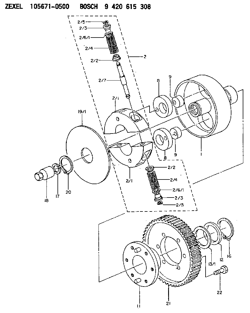
| 1. | [1] | 156700-1600 | FLANGE BUSHING |
| 2. | [1] | 156718-3420 | FLYWEIGHT ASSEMBLY |
| 2/1. | [2] | 156702-7120 | FLYWEIGHT |
| 2/1. | [2] | 156702-7120 | FLYWEIGHT |
| 2/2. | [4] | 156707-0100 | SLOTTED WASHER |
| 2/2. | [4] | 156707-0100 | SLOTTED WASHER |
| 2/3. | [4] | 156707-0000 | SLOTTED WASHER |
| 2/3. | [4] | 156707-0000 | SLOTTED WASHER |
| 2/4. | [4] | 156714-6900 | COMPRESSION SPRING |
| 2/4. | [4] | 156714-6900 | COMPRESSION SPRING |
| 2/5. | [4] | 156709-0200 | LOCKING WASHER |
| 2/5. | [4] | 156709-0200 | LOCKING WASHER |
| 2/6/1. | [0] | 156708-3600 | SHIM D15.5&11.5T0.1 |
| 2/6/1. | [0] | 156708-3700 | SHIM D15.5&11.5T0.2 |
| 2/6/1. | [0] | 156708-3800 | SHIM D15.5&11.5T0.3 |
| 2/6/1. | [0] | 156708-3900 | SHIM D15.5&11.5T0.4 |
| 2/6/1. | [0] | 156708-4000 | SHIM D15.5&11.5T0.5 |
| 2/6/1. | [0] | 156708-4100 | SHIM D15.5&11.5T0.6 |
| 2/6/1. | [0] | 156708-4200 | SHIM D15.5&11.5T0.7 |
| 2/6/1. | [0] | 156708-4300 | SHIM D15.5&11.5T0.8 |
| 2/6/1. | [0] | 156708-4400 | SHIM D15.5&11.5T0.9 |
| 2/6/1. | [0] | 156708-4500 | SHIM D15.5&11.5T1.0 |
| 2/6/1. | [0] | 156708-4500 | SHIM D15.5&11.5T1.0 |
| 2/7. | [2] | 156706-0000 | PIN |
| 8. | [2] | 156703-0500 | ECCENTRIC DISC |
| 8. | [2] | 156703-0500 | ECCENTRIC DISC |
| 9. | [2] | 156703-0600 | ECCENTRIC DISC |
| 9. | [2] | 156703-0600 | ECCENTRIC DISC |
| 11. | [1] | 156701-0020 | FLANGE BUSHING |
| 12. | [1] | 156708-0000 | SHIM D46.0&34.1T2.85 |
| 13/1. | [0] | 156708-0100 | SHIM D46.0&34.1T0.1 |
| 13/1. | [0] | 156708-0200 | SHIM D46.0&34.1T0.12 |
| 13/1. | [0] | 156708-0300 | SHIM D46.0&34.1T0.14 |
| 13/1. | [0] | 156708-0400 | SHIM D46.0&34.1T0.16 |
| 13/1. | [0] | 156708-0500 | SHIM D46.0&34.1T0.18 |
| 13/1. | [0] | 156708-0600 | SHIM D46.0&34.1T0.2 |
| 13/1. | [0] | 156708-0700 | SHIM D46.0&34.1T0.3 |
| 16. | [1] | 016020-3420 | LOCKING WASHER |
| 17. | [1] | 156709-1000 | LOCKING WASHER |
| 18. | [1] | 131325-2300 | UNION NUT |
| 19/1. | [0] | 156708-1800 | SHIM D104&26.2T1.9 |
| 19/1. | [0] | 156708-1900 | SHIM D104&26.2T2.0 |
| 19/1. | [0] | 156708-2000 | SHIM D104&26.2T2.1 |
| 20. | [1] | 016020-2620 | LOCKING WASHER |
| 21. | [1] | 156221-7500 | TOOTHED GEAR |
| 22. | [6] | 139006-5600 | BLEEDER SCREW |
Include in #1:
101401-9670
as AUTOM. ADVANCE MECHANIS
Cross reference number
Zexel num
Bosch num
Firm num
Name
105671-0500
1681017D72 NISSAN
AUTOM. ADVANCE MECHANISM
K 14KJ AUTOMATIC TIMER TIMER SCDM TIMER
K 14KJ AUTOMATIC TIMER TIMER SCDM TIMER
105671-0500
1681017D72 NISSAN-DIESEL
AUTOM. ADVANCE MECHANISM
K 14KJ AUTOMATIC TIMER TIMER SCDM TIMER
K 14KJ AUTOMATIC TIMER TIMER SCDM TIMER
Information:
Start By:a. remove valve covers 1. Loosen the fuel injection line nut at the nozzle end with tool (A).2. Loosen the fuel line nut at the fuel injection line adapter with tool (B). Remove inner fuel injection lines (1). Install caps and plugs on all fuel injection line openings to keep dirt out of the fuel system. If necessary, use tooling (D) to turn the engine so the valves do not make contact with the pistons when the valves are opened with tool (C) to remove the push rods.3. Put compression on the valve springs with tool (C). And remove push rods (2). Put identification mark on the push rods as to their location in the engine.4. Push the push rod end of the rocker arms down. 5. Remove the intake valve lifter with tooling (E) as follows:a. Install 5P2685 Nut (3) and 5P6601 Collet (4) on 5P2408 Outer Handle Assembly (5).b. Install 5P6599 Inner Handle Assembly (6) in 5P2408 Outer Handle Assembly (5). c. Install tooling (E) in the intake valve lifter. Hold the 5P2408 Outer Handle Assembly, and tighten the 5P6599 Inner Handle Assembly until the 5P6601 Collet is tight against the inside of the intake valve lifter. d. Remove intake valve lifters (7) from the cylinder block with tooling (E). Put identification marks on the lifters as to their location in the engine. 6. Remove the exhaust valve filters with tooling (E) as follows:a. Install 5P2685 Nut (3) and 5P6601 Collet (4) on 5P2408 Outer Handle Assembly (5). The opening in the cylinder head assembly for the intake valve lifter is larger than the opening in the exhaust valve lifter side. The tooling and each valve lifter must be installed and removed from the intake valve lifter side.b. Install the outer handle assembly in the intake valve lifter side of the cylinder head assembly. Slide the flat area of 5P2408 Outer Handle Assembly (5) through the head casting, and install the 5P6601 Collet in the exhaust valve lifters. c. Install 5P6599 Inner Handle Assembly (6) in 5P2408 Outer Handle Assembly (5). Hold the 5P2408 Handle Assembly, and tighten the 5P6599 Handle Assembly until the 5P6601 Collet is tight against the inside of the exhaust valve lifter.d. Pull the exhaust valve lifter up until the spring on the exhaust valve lifter is free from the cylinder block.e. Remove the 5P6599 Inner Handle Assembly through the head casting, and remove it from the intake valve lifter side of the cylinder head. f. Use a magnet, and remove exhaust valve lifters (8) from the intake valve lifter side of the cylinder head assembly. Put identification marks on the lifters as to their location on the engine.7. Remove the guide springs from the lifters.Install Valve Lifters
Steps 1 and 2 must be done to install intake or exhaust valve lifters.
Make sure
Steps 1 and 2 must be done to install intake or exhaust valve lifters.
Make sure