Information autom. advance mechanism
BOSCH
9 420 615 704
9420615704
ZEXEL
105671-0210
1056710210
ISUZU
8970617860
8970617860
Rating:
Scheme ###:
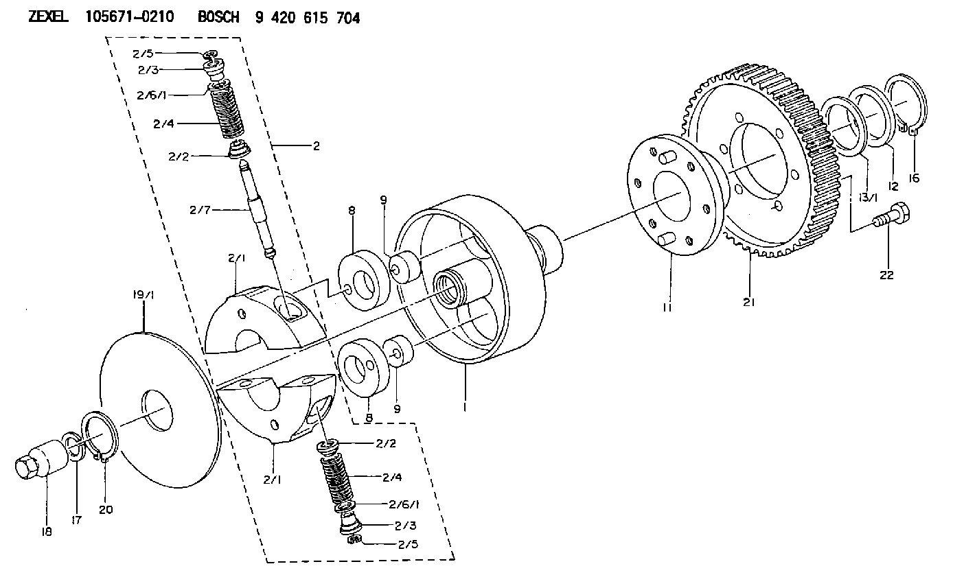
| 1. | [1] | 156700-0000 | FLANGE BUSHING |
| 2. | [1] | 156710-9420 | FLYWEIGHT ASSEMBLY |
| 2/1. | [2] | 156702-8720 | FLYWEIGHT |
| 2/1. | [2] | 156702-8720 | FLYWEIGHT |
| 2/2. | [4] | 156707-0100 | SLOTTED WASHER |
| 2/2. | [4] | 156707-0100 | SLOTTED WASHER |
| 2/3. | [4] | 156707-0000 | SLOTTED WASHER |
| 2/3. | [4] | 156707-0000 | SLOTTED WASHER |
| 2/4. | [4] | 156705-2400 | COMPRESSION SPRING |
| 2/4. | [4] | 156705-2400 | COMPRESSION SPRING |
| 2/5. | [4] | 156709-0200 | LOCKING WASHER |
| 2/5. | [4] | 156709-0200 | LOCKING WASHER |
| 2/6/1. | [0] | 156708-3600 | SHIM D15.5&11.5T0.1 |
| 2/6/1. | [0] | 156708-3700 | SHIM D15.5&11.5T0.2 |
| 2/6/1. | [0] | 156708-3800 | SHIM D15.5&11.5T0.3 |
| 2/6/1. | [0] | 156708-3800 | SHIM D15.5&11.5T0.3 |
| 2/6/1. | [0] | 156708-3900 | SHIM D15.5&11.5T0.4 |
| 2/6/1. | [0] | 156708-4000 | SHIM D15.5&11.5T0.5 |
| 2/6/1. | [0] | 156708-4100 | SHIM D15.5&11.5T0.6 |
| 2/6/1. | [0] | 156708-4200 | SHIM D15.5&11.5T0.7 |
| 2/6/1. | [0] | 156708-4300 | SHIM D15.5&11.5T0.8 |
| 2/6/1. | [0] | 156708-4400 | SHIM D15.5&11.5T0.9 |
| 2/6/1. | [0] | 156708-4500 | SHIM D15.5&11.5T1.0 |
| 2/7. | [2] | 156706-0000 | PIN |
| 8. | [2] | 156703-0500 | ECCENTRIC DISC |
| 8. | [2] | 156703-0500 | ECCENTRIC DISC |
| 9. | [2] | 156703-0600 | ECCENTRIC DISC |
| 9. | [2] | 156703-0600 | ECCENTRIC DISC |
| 11. | [1] | 156701-0220 | FLANGE BUSHING |
| 12. | [1] | 156708-0000 | SHIM D46.0&34.1T2.85 |
| 13/1. | [0] | 156708-0100 | SHIM D46.0&34.1T0.1 |
| 13/1. | [0] | 156708-0200 | SHIM D46.0&34.1T0.12 |
| 13/1. | [0] | 156708-0300 | SHIM D46.0&34.1T0.14 |
| 13/1. | [0] | 156708-0400 | SHIM D46.0&34.1T0.16 |
| 13/1. | [0] | 156708-0500 | SHIM D46.0&34.1T0.18 |
| 13/1. | [0] | 156708-0600 | SHIM D46.0&34.1T0.2 |
| 13/1. | [0] | 156708-0700 | SHIM D46.0&34.1T0.3 |
| 16. | [1] | 016020-3420 | LOCKING WASHER |
| 17. | [1] | 156709-1000 | LOCKING WASHER |
| 18. | [1] | 131325-3200 | UNION NUT |
| 19/1. | [0] | 156708-1800 | SHIM D104&26.2T1.9 |
| 19/1. | [0] | 156708-1900 | SHIM D104&26.2T2.0 |
| 19/1. | [0] | 156708-2000 | SHIM D104&26.2T2.1 |
| 20. | [1] | 016020-2620 | LOCKING WASHER |
| 21. | [1] | 156211-9000 | TOOTHED GEAR |
| 22. | [6] | 139006-4300 | BLEEDER SCREW |
Include in #1:
101401-4240
as AUTOM. ADVANCE MECHANIS
Cross reference number
Zexel num
Bosch num
Firm num
Name
9 420 615 704
8970617860 ISUZU
AUTOM. ADVANCE MECHANISM
* K 14KJ TIMER SCDM TIMER
* K 14KJ TIMER SCDM TIMER
Information:
Illustration 8: (12) Injection plunger. (13) Plunger gear. (G) Location. (H) Location.1. Inspect injection plunger (12), especially at scroll location (G).Any scratches, rust, or erosion (uneven wear) at location (G) can be an indication that the unit injector will not pump the correct amount of fuel.If a scratch, rust, etc. at location (G) can be felt with your fingernail, the plunger is worn too much and the unit injector should be replaced.2. Some surface conditions to look for at location (G) are: SCRATCHES: Scratches are caused by dirt in the fuel or other foreign material that get into the unit injector.RUST DAMAGE: Rust damage that is caused either by water in the fuel, or by incorrect storage procedures for unit injectors.CAVITATION EROSION: The surface condition of the plunger, especially in the area of location (G), will look and feel similar to emery cloth.This condition is normally seen in a unit injector that has high operating hours, and is caused by the constant impact of high velocity fuel as it strikes the surface of the plunger.3. Surface defects away from the scroll area are less likely to affect fuel delivery but can cause sticking or seizure of the plunger. Any condition that causes the plunger to stick or bind is NOT acceptable.Place the plunger in clean test fluid to ensure good lubrication before checking the plunger movement.If the plunger still sticks, the unit injector should be replaced. A plunger can look satisfactory and not stick; but still be worn too much to deliver the correct amount of fuel. It may also leak. Usually, if a plunger looks good and feels good, it probably is in good condition.4. It is normal for plunger gear (13) to have wear mark(s) or polished area(s) on the gear teeth at [location (H)] that is caused by contact with rack (15).If the wear marks at each location (H) can be felt with the point of a pencil, or if the teeth are worn to a sharp edge, the gear is worn too much.Cleaning Of Unit Injector Barrel
Illustration 9: (1) Case. (2) Unit injector body. (3) Tappet spring. (4) Tip assembly (part of check assembly). (5) Check (part of check assembly). (6) Stop (part of check assembly). (7) Sleeve (part of check assembly). (8) Spill deflector. (9) Spring (check). (10) Plate. (11) Barrel (part of plunger assembly). (12) Injector plunger (part of plunger assembly). (13) Plunger gear (part of plunger assembly). (14) Retainer. (15) Rack. (16) Tappet retainer pin. (17) Keeper. (18) Tappet assembly.1. Place a unit injector body in Pedestal (Tool B) with the tip up.This will allow cleaning fluid to drain from barrel (11).2. Flush barrel (11) with cleaning solution filtered to the 5 micron level.Use clean 6V-6067 or 6V-6068 Test Fluid or equivalent test fluid that meets SAE967 or ISO4113 Standards as a cleaning solution.A 6V-7093 Brush Assembly can be used to remove varnish deposits.Do NOT remove barrel (11) from the unit injector. The barrel can NOT be removed from the unit