Information autom. advance mechanism
BOSCH
9 420 615 454
9420615454
ZEXEL
105671-0191
1056710191
ISUZU
8971046651
8971046651
Rating:
Scheme ###:
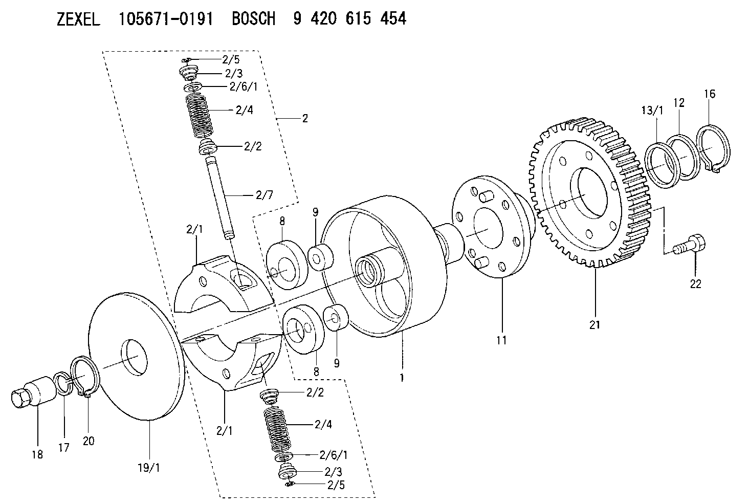
| 1. | [1] | 156700-0000 | FLANGE BUSHING |
| 2. | [1] | 156710-1720 | FLYWEIGHT ASSEMBLY |
| 2/1. | [2] | 156702-9520 | FLYWEIGHT |
| 2/1. | [2] | 156702-9520 | FLYWEIGHT |
| 2/2. | [4] | 156707-0100 | SLOTTED WASHER |
| 2/2. | [4] | 156707-0100 | SLOTTED WASHER |
| 2/3. | [4] | 156707-0000 | SLOTTED WASHER |
| 2/3. | [4] | 156707-0000 | SLOTTED WASHER |
| 2/4. | [4] | 156704-4100 | COMPRESSION SPRING |
| 2/4. | [4] | 156704-4100 | COMPRESSION SPRING |
| 2/5. | [4] | 156709-0200 | LOCKING WASHER |
| 2/5. | [4] | 156709-0200 | LOCKING WASHER |
| 2/6/1. | [0] | 156708-3600 | SHIM D15.5&11.5T0.1 |
| 2/6/1. | [0] | 156708-3600 | SHIM D15.5&11.5T0.1 |
| 2/6/1. | [0] | 156708-3700 | SHIM D15.5&11.5T0.2 |
| 2/6/1. | [0] | 156708-3800 | SHIM D15.5&11.5T0.3 |
| 2/6/1. | [0] | 156708-3900 | SHIM D15.5&11.5T0.4 |
| 2/6/1. | [0] | 156708-4000 | SHIM D15.5&11.5T0.5 |
| 2/6/1. | [0] | 156708-4100 | SHIM D15.5&11.5T0.6 |
| 2/6/1. | [0] | 156708-4200 | SHIM D15.5&11.5T0.7 |
| 2/6/1. | [0] | 156708-4300 | SHIM D15.5&11.5T0.8 |
| 2/6/1. | [0] | 156708-4400 | SHIM D15.5&11.5T0.9 |
| 2/6/1. | [0] | 156708-4500 | SHIM D15.5&11.5T1.0 |
| 2/7. | [2] | 156706-0000 | PIN |
| 8. | [2] | 156703-0500 | ECCENTRIC DISC |
| 8. | [2] | 156703-0500 | ECCENTRIC DISC |
| 9. | [2] | 156703-0600 | ECCENTRIC DISC |
| 9. | [2] | 156703-0600 | ECCENTRIC DISC |
| 11. | [1] | 156701-0220 | FLANGE BUSHING |
| 12. | [1] | 156708-0000 | SHIM D46.0&34.1T2.85 |
| 13/1. | [0] | 156708-0100 | SHIM D46.0&34.1T0.1 |
| 13/1. | [0] | 156708-0200 | SHIM D46.0&34.1T0.12 |
| 13/1. | [0] | 156708-0300 | SHIM D46.0&34.1T0.14 |
| 13/1. | [0] | 156708-0400 | SHIM D46.0&34.1T0.16 |
| 13/1. | [0] | 156708-0500 | SHIM D46.0&34.1T0.18 |
| 13/1. | [0] | 156708-0600 | SHIM D46.0&34.1T0.2 |
| 13/1. | [0] | 156708-0700 | SHIM D46.0&34.1T0.3 |
| 16. | [1] | 016020-3420 | LOCKING WASHER |
| 17. | [1] | 156709-1000 | LOCKING WASHER |
| 18. | [1] | 131325-2300 | UNION NUT |
| 19/1. | [0] | 156708-1800 | SHIM D104&26.2T1.9 |
| 19/1. | [0] | 156708-1900 | SHIM D104&26.2T2.0 |
| 19/1. | [0] | 156708-2000 | SHIM D104&26.2T2.1 |
| 20. | [1] | 016020-2620 | LOCKING WASHER |
| 21. | [1] | 156211-6500 | TOOTHED GEAR |
| 22. | [6] | 139006-4300 | BLEEDER SCREW |
Cross reference number
Zexel num
Bosch num
Firm num
Name
105671-0191
8971046651 ISUZU
AUTOM. ADVANCE MECHANISM
K 14KJ AUTOMATIC TIMER TIMER SCDM TIMER
K 14KJ AUTOMATIC TIMER TIMER SCDM TIMER
Information:
Introduction
Tools are now available for the 6V4830 Fixture Group for removal and replacement of tappet springs on 3500 Unit Injectors.
Type 2 Fuel Injector. (1) Spring. (2) Rack Bar.
(3) 6V4830 Fixture Group. (4) 4C9279 Plate Assembly.Use fixture group (3) and plate assembly (4) along with the procedure in this instruction to remove and install tappet springs on injectors.Do not perform any procedure, outlined in this publication, or order any parts until you read and understand the information contained within.Removal and Installation of Fuel Injector Tappet Springs
Take care not to damage, drop, or jar the internal parts of the injector. Injector parts must be clean when reassembled. Place a light coating of clean diesel fuel, kerosene, or calibration fluid on the moving internal components during assembly.
* Clean the outside of the injector before disassembly. Install good O-ring seals on the injector and then install a 6V4172 Cleaning Sleeve. Wash the outside of the injector with solvents and a brush. Dry with pressure air.
Pressure air can cause personal injury. When using pressure air for cleaning, wear a protective face shield, protective clothing and protective shoes.The maximum air pressure must be below 205 kPa (30 psi) for cleaning purposes.
1. Remove existing plate and secure plate assembly (4) to fixture group (3).2. Remove O-ring seals from the injector prior to placing injector into fixture.3. Place injector into fixture with spring up as shown. Rack bar (2) on injector is to be extended out so that it is locked into position by two pins on plate assembly (4). 4. Using the handle of the fixture group, compress injector spring (tappet) (5) so that lock pin (6) can be pushed IN to release the tappet assembly from the injector body. 5. Remove tappet assembly from the injector body. Remove and discard old spring. Place the injector plunger on a soft clean cloth to avoid handling the plunger. Excessive handling will remove the fuel on the plunger and may result in corroding the plunger if it is left out for an extended period of time.6. Install new spring on injector body. 7. Locate the punched dot (.)(7) on the top end of the gear after it is pulled out of the body. Using a yellow magic marker, paint the whole length of the tooth that is 180° opposite the punched dot.
Injector Assembly (shown without spring).8. As the tappet/plunger assembly is inserted into the body, the yellow colored tooth on the gear should be visible in the center of the slot for the tappet lock pin.
Injector Assembly (shown without spring). 9. With the colored tooth visible in the slot of the injector body, a pin or long narrow screw driver is needed to position the gear to engage rack and pinion teeth after which the tappet assembly will drop into place.10. Using the 6V4830 Fixture Group, apply pressure on tappet (5) to compress the spring so the pin pops out and locks the tappet assembly in place.11. Remove the injector from the fixture. Push and pull the