Information autom. advance mechanism
BOSCH
9 420 615 802
9420615802
ZEXEL
105671-0120
1056710120
ISUZU
8970248910
8970248910

Rating:
Scheme ###:
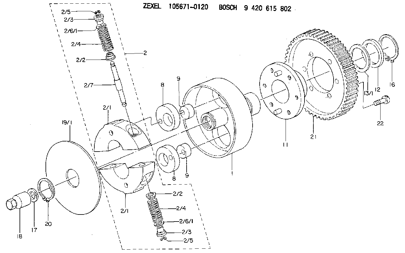
| 1. | [1] | 156700-0000 | FLANGE BUSHING |
| 2. | [1] | 156710-7520 | FLYWEIGHT ASSEMBLY |
| 2/1. | [2] | 156702-7920 | FLYWEIGHT |
| 2/1. | [2] | 156702-7920 | FLYWEIGHT |
| 2/2. | [4] | 156707-0100 | SLOTTED WASHER |
| 2/2. | [4] | 156707-0100 | SLOTTED WASHER |
| 2/3. | [4] | 156707-0000 | SLOTTED WASHER |
| 2/3. | [4] | 156707-0000 | SLOTTED WASHER |
| 2/4. | [4] | 156705-6700 | COMPRESSION SPRING |
| 2/4. | [4] | 156705-6700 | COMPRESSION SPRING |
| 2/5. | [4] | 156709-0200 | LOCKING WASHER |
| 2/5. | [4] | 156709-0200 | LOCKING WASHER |
| 2/6/1. | [0] | 156708-3600 | SHIM D15.5&11.5T0.1 |
| 2/6/1. | [0] | 156708-3700 | SHIM D15.5&11.5T0.2 |
| 2/6/1. | [0] | 156708-3800 | SHIM D15.5&11.5T0.3 |
| 2/6/1. | [0] | 156708-3900 | SHIM D15.5&11.5T0.4 |
| 2/6/1. | [0] | 156708-4000 | SHIM D15.5&11.5T0.5 |
| 2/6/1. | [0] | 156708-4000 | SHIM D15.5&11.5T0.5 |
| 2/6/1. | [0] | 156708-4100 | SHIM D15.5&11.5T0.6 |
| 2/6/1. | [0] | 156708-4200 | SHIM D15.5&11.5T0.7 |
| 2/6/1. | [0] | 156708-4300 | SHIM D15.5&11.5T0.8 |
| 2/6/1. | [0] | 156708-4400 | SHIM D15.5&11.5T0.9 |
| 2/6/1. | [0] | 156708-4500 | SHIM D15.5&11.5T1.0 |
| 2/7. | [2] | 156706-0000 | PIN |
| 8. | [2] | 156703-0500 | ECCENTRIC DISC |
| 8. | [2] | 156703-0500 | ECCENTRIC DISC |
| 9. | [2] | 156703-0600 | ECCENTRIC DISC |
| 9. | [2] | 156703-0600 | ECCENTRIC DISC |
| 11. | [1] | 156701-0220 | FLANGE BUSHING |
| 12. | [1] | 156708-0000 | SHIM D46.0&34.1T2.85 |
| 13/1. | [0] | 156708-0100 | SHIM D46.0&34.1T0.1 |
| 13/1. | [0] | 156708-0200 | SHIM D46.0&34.1T0.12 |
| 13/1. | [0] | 156708-0300 | SHIM D46.0&34.1T0.14 |
| 13/1. | [0] | 156708-0400 | SHIM D46.0&34.1T0.16 |
| 13/1. | [0] | 156708-0500 | SHIM D46.0&34.1T0.18 |
| 13/1. | [0] | 156708-0600 | SHIM D46.0&34.1T0.2 |
| 13/1. | [0] | 156708-0700 | SHIM D46.0&34.1T0.3 |
| 16. | [1] | 016020-3420 | LOCKING WASHER |
| 17. | [1] | 156709-1000 | LOCKING WASHER |
| 18. | [1] | 131325-3201 | UNION NUT |
| 19/1. | [0] | 156708-1800 | SHIM D104&26.2T1.9 |
| 19/1. | [0] | 156708-1900 | SHIM D104&26.2T2.0 |
| 19/1. | [0] | 156708-2000 | SHIM D104&26.2T2.1 |
| 20. | [1] | 016020-2620 | LOCKING WASHER |
| 21. | [1] | 156211-6000 | TOOTHED GEAR |
| 22. | [6] | 139006-4300 | BLEEDER SCREW |
Include in #1:
101491-0520
as AUTOM. ADVANCE MECHANIS
Cross reference number
Zexel num
Bosch num
Firm num
Name
105671-0120
9 420 615 802
8970248910 ISUZU
AUTOM. ADVANCE MECHANISM
* K
* K
Information:
(3) Remove all dirt, rust and foreign material from the surfaces on transmission input flange (3), shaft assembly (4) and spacer group (2). Use a file to remove all burrs or damaged areas on the surfaces. Install shaft assembly (4) on flange (3) with bolts (5) and the nuts. Push the crankshaft to the front of its travel with a pry bar. Loosely install spacer (2). Put a feeler gauge equal to one-half the crankshaft end play (see step 2, page 6 for the dimension) between spacer (2) and coupling (1) at (S). Move the engine to the front or rear as needed to get clearance equal to the feeler gauge thickness. Remove spacer (2). Install 6V2042 Alignment Yoke (6) and 6V2043 Alignment Bar (7) on shaft (4) with two 13.0 mm Ø (.5"Ø) threaded rods and nuts. Install two dial indicators (8) and (9) as shown, one on surface (Y) and one on surface (Z). Use a pry bar to push the crankshaft to the front of its travel. Set the indicators to "0" in this position. (4) Indicator (8), on surface (Y), will show face alignment. Slowly turn shaft (4) by hand; do not use yoke (6) to turn the shaft. Make a record of the indicator readings 90° apart at (A), (B), (C) and (D). Face alignment as shown by the indicator must be as follows: a) A maximum TIR between (A) and (C) of 0.25 mm (.010") is permitted. The reading at (C) must be plus (+). This dimension is needed, because as an application of engine torque is made to the propeller shaft, the transmission will tip forward a small amount and both dimensions will be the same.b) A maximum TIR between (B) and (D) of 0.25 mm (0.010") is permitted but the reading at (B) plus the reading at (D) must be equal to the reading at (C). (5) Indicator (9) on surface (Z) will show bore alignment. Put the indicator on "0" at location (A). Slowly turn shaft (4) and make a record of the indicator readings 90° apart at (A), (B), (C) and (D). Bore alignment as shown by indicator (9) must be as follows: a) The TIR between (A) and (C) must be 0.64 0.25 mm (.025" .010"). IMPORTANT: Because the centerline of the crankshaft must be below the centerline of the coupling shaft, the indicator reading at (C) must be plus (+) when the reading at (A) is 0.00 mm (.000") and indicator (9) is installed as shown.b) The TIR between (B) and (D) can be a maximum of 0.13 (.005"). The reading at (B) plus (D) must equal the reading at (C).(6) Move the engine as necessary to get the alignment dimensions given. (7) Loosely connect shaft (4) to coupling (1) with two bolts (18). Do not install the spacer between the shaft and the coupling at this time. Rotate the engine and transmission input shaft together and take the dial indicator readings
Have questions with 105671-0120?
Group cross 105671-0120 ZEXEL
Isuzu
105671-0120
9 420 615 802
8970248910
AUTOM. ADVANCE MECHANISM