Information autom. advance mechanism
BOSCH
9 420 616 514
9420616514
ZEXEL
105645-5010
1056455010
NISSAN-DIESEL
1685197005
1685197005

Rating:
Scheme ###:
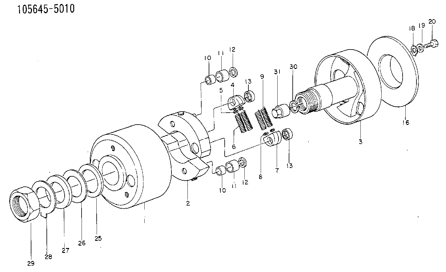
| 1. | [1] | 156300-0722 | TIMING-DEVICE HOUSING |
| 2. | [2] | 156305-1520 | FLYWEIGHT |
| 3. | [1] | 156302-2220 | FLANGE BUSHING |
| 4. | [2] | 156310-0000 | SLOTTED WASHER |
| 5/1. | [0] | 029310-8520 | SHIM D14&8.4T0.2 |
| 5/1. | [0] | 029310-8530 | SHIM D14&8.4T0.4 |
| 5/1. | [0] | 029310-8540 | SHIM D14&8.4T0.5 |
| 5/1. | [0] | 029310-8550 | SHIM D14&8.4T0.6 |
| 5/1. | [0] | 029310-8560 | SHIM D14&8.4T0.7 |
| 5/1. | [0] | 029310-8680 | SHIM D14&8.4T1.0 |
| 5/1. | [0] | 139408-0000 | SHIM D14&8.4T0.30 |
| 5/1. | [0] | 139408-0100 | SHIM D14&8.4T0.80 |
| 5/1. | [0] | 139408-0200 | SHIM D14&8.4T0.90 |
| 5/1. | [0] | 139408-0300 | SHIM D14&8.4T0.10 |
| 5/1. | [0] | 139408-0500 | SHIM D14&8.4T1.5 |
| 5/1. | [0] | 139408-0600 | SHIM D14&8.4T2.0 |
| 6. | [2] | 156311-4500 | COMPRESSION SPRING |
| 7. | [2] | 156310-0100 | SLOTTED WASHER |
| 8/1. | [0] | 029310-8520 | SHIM D14&8.4T0.2 |
| 8/1. | [0] | 029310-8530 | SHIM D14&8.4T0.4 |
| 8/1. | [0] | 029310-8540 | SHIM D14&8.4T0.5 |
| 8/1. | [0] | 029310-8550 | SHIM D14&8.4T0.6 |
| 8/1. | [0] | 029310-8560 | SHIM D14&8.4T0.7 |
| 8/1. | [0] | 029310-8680 | SHIM D14&8.4T1.0 |
| 8/1. | [0] | 139408-0000 | SHIM D14&8.4T0.30 |
| 8/1. | [0] | 139408-0100 | SHIM D14&8.4T0.80 |
| 8/1. | [0] | 139408-0200 | SHIM D14&8.4T0.90 |
| 8/1. | [0] | 139408-0300 | SHIM D14&8.4T0.10 |
| 8/1. | [0] | 139408-0500 | SHIM D14&8.4T1.5 |
| 8/1. | [0] | 139408-0600 | SHIM D14&8.4T2.0 |
| 9. | [2] | 156311-4600 | COMPRESSION SPRING |
| 10. | [2] | 156312-0000 | BUSHING |
| 10. | [2] | 156312-0000 | BUSHING |
| 11/1. | [1] | 156313-0000 | ROLLER D23.9 |
| 11/1. | [1] | 156313-0000 | ROLLER D23.9 |
| 11/1. | [1] | 156313-0100 | ROLLER D24.0 |
| 11/1. | [1] | 156313-0200 | ROLLER D24.1 |
| 11/1. | [1] | 156313-0300 | ROLLER D24.2 |
| 12. | [2] | 029301-2250 | PLAIN WASHER D23&12T3.5 |
| 12. | [2] | 029301-2250 | PLAIN WASHER D23&12T3.5 |
| 13. | [2] | 156317-0000 | RETAINER |
| 13. | [2] | 156317-0000 | RETAINER |
| 16. | [1] | 156308-0400 | COVER |
| 18. | [2] | 156210-1200 | LOCKING LEVER |
| 19. | [2] | 156615-2000 | PLAIN WASHER |
| 20. | [2] | 156603-9500 | BLEEDER SCREW |
| 25. | [1] | 156269-0100 | PLAIN WASHER |
| 26/1. | [0] | 029315-2000 | SHIM D70&52.2T0.1 |
| 26/1. | [0] | 029315-2010 | SHIM D70&52.2T0.12 |
| 26/1. | [0] | 029315-2020 | SHIM D70&52.2T0.15 |
| 26/1. | [0] | 029315-2030 | SHIM D70&52.2T0.2 |
| 26/1. | [0] | 029315-2040 | SHIM D70&52.2T0.3 |
| 27. | [1] | 029304-8000 | PLAIN WASHER |
| 28. | [1] | 156270-0100 | LOCKING LEVER |
| 29. | [1] | 029204-8000 | UNION NUT |
| 30. | [1] | 029321-8020 | LOCKING WASHER |
| 31. | [1] | 134325-0100 | UNION NUT |
Cross reference number
Zexel num
Bosch num
Firm num
Name
1685197005 NISSAN-DIESEL
AUTOM. ADVANCE MECHANISM
* K 14KD AUTOMATIC TIMER TIMER SP(Z) TIMER
* K 14KD AUTOMATIC TIMER TIMER SP(Z) TIMER
Information:
(1) Large bolts (3/4 inch). Put 6V4876 Molycoat on all bolt threads and under all bolt heads. Tighten the bolts in the following step sequence:Step 1. Tighten bolts from 1 through 20 in number sequence to ... 270 25 N m (200 20 lb ft)Step 2. Tighten bolts from 1 through 20 in number sequence to ... 450 20 N m (330 15 lb ft)Step 3. Tighten bolts from 1 through 20 in number sequence again to ... 450 20 N m (330 15 lb ft)Step 4. Install the rocker arm shafts for the engine valves.Step 5. Tighten bolts from 21 through 26 in number sequence to ... 270 25 N m (200 20 lb ft)Step 6. Tighten bolts from 21 through 26 in number sequence to ... 450 20 N m (330 15 lb ft)Step 7. Tighten bolts from 21 through 26 in number sequence again to ... 450 20 N m (330 15 lb ft)Step 8. Tighten the twelve small bolts (2) to ... 45 7 N m (33 5 lb ft)(2) Small bolts (3/8 inch). See Step 8 above.(3) Torque for twelve studs in cylinder head ... 30 5 N m (22 4 lb ft) (4) Thickness of cylinder head (new) ... 112.78 0.25 mm (4.440 .010 in) Minimum permissible thickness of cylinder head ... 111.51 mm (4.390 in)(5) Torque for six studs that hold fuel line adapter locks ... 30 5 N m (22 4 lb ft) Flatness of the cylinder head should be within 0.13 mm (.005 in) total, and a maximum of 0.03 mm (.001 in) for any 76.2 mm (3.00 in) span.
When the cylinder head is installed on an engine with a water cooled exhaust manifold, plug (A) MUST be removed to prevent damage to the water cooled exhaust manifold. If the engine has a dry exhaust manifold, plug (A) MUST NOT be removed.
When the cylinder head is installed on an engine with a water cooled exhaust manifold, plug (A) MUST be removed to prevent damage to the water cooled exhaust manifold. If the engine has a dry exhaust manifold, plug (A) MUST NOT be removed.