Information autom. advance mechanism
BOSCH
9 420 616 332
9420616332
ZEXEL
105644-0550
1056440550
Rating:
Scheme ###:
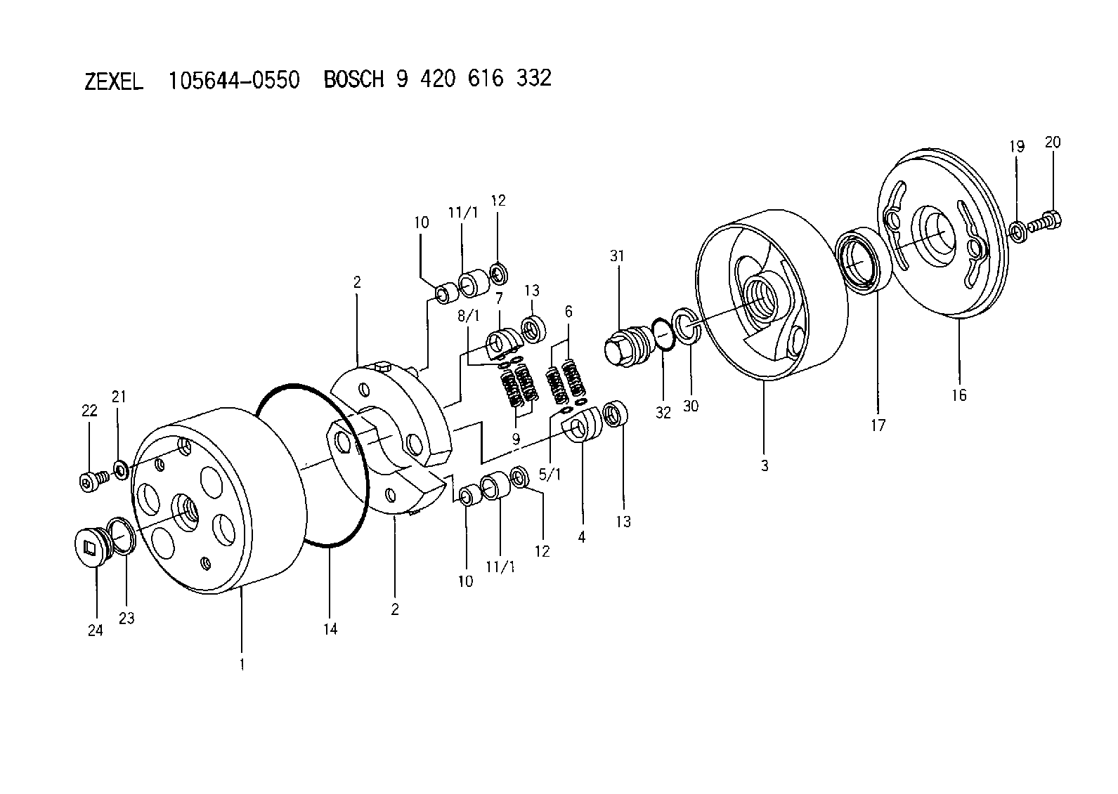
| 1. | [1] | 156400-0820 | TIMING-DEVICE HOUSING |
| 2. | [2] | 156405-0420 | FLYWEIGHT |
| 2. | [2] | 156405-0420 | FLYWEIGHT |
| 3. | [1] | 156423-1720 | FLANGE BUSHING |
| 4. | [2] | 156410-0300 | SLOTTED WASHER |
| 5/1. | [0] | 029310-6220 | SHIM D11.5&6.5T0.10 |
| 5/1. | [0] | 029310-6230 | SHIM D11.5&6.5T0.20 |
| 5/1. | [0] | 029310-6240 | SHIM D11.5&6.5T0.25 |
| 5/1. | [0] | 029310-6250 | SHIM D11.5&6.5T1.00 |
| 5/1. | [0] | 029310-6370 | SHIM D11.5&6.5T0.30 |
| 5/1. | [0] | 029310-6380 | SHIM D11.5&6.5T0.40 |
| 5/1. | [0] | 029310-6390 | SHIM D11.5&6.5T0.50 |
| 5/1. | [0] | 029310-6400 | SHIM D11.5&6.5T0.60 |
| 5/1. | [0] | 029310-6410 | SHIM D11.5&6.5T0.70 |
| 5/1. | [0] | 029310-6420 | SHIM D11.5&6.5T0.80 |
| 5/1. | [0] | 029310-6430 | SHIM D11.5&6.5T0.90 |
| 5/1. | [0] | 139406-0500 | SHIM D11.5&6.5T1.5 |
| 5/1. | [0] | 139406-0600 | SHIM D11.5&6.5T2.0 |
| 6. | [2] | 156421-9500 | COMPRESSION SPRING |
| 7. | [2] | 156410-0300 | SLOTTED WASHER |
| 8/1. | [0] | 029310-6220 | SHIM D11.5&6.5T0.10 |
| 8/1. | [0] | 029310-6230 | SHIM D11.5&6.5T0.20 |
| 8/1. | [0] | 029310-6240 | SHIM D11.5&6.5T0.25 |
| 8/1. | [0] | 029310-6250 | SHIM D11.5&6.5T1.00 |
| 8/1. | [0] | 029310-6370 | SHIM D11.5&6.5T0.30 |
| 8/1. | [0] | 029310-6380 | SHIM D11.5&6.5T0.40 |
| 8/1. | [0] | 029310-6390 | SHIM D11.5&6.5T0.50 |
| 8/1. | [0] | 029310-6400 | SHIM D11.5&6.5T0.60 |
| 8/1. | [0] | 029310-6410 | SHIM D11.5&6.5T0.70 |
| 8/1. | [0] | 029310-6420 | SHIM D11.5&6.5T0.80 |
| 8/1. | [0] | 029310-6430 | SHIM D11.5&6.5T0.90 |
| 8/1. | [0] | 139406-0500 | SHIM D11.5&6.5T1.5 |
| 8/1. | [0] | 139406-0600 | SHIM D11.5&6.5T2.0 |
| 9. | [2] | 156421-9500 | COMPRESSION SPRING |
| 10. | [2] | 156412-0100 | BUSHING |
| 10. | [2] | 156412-0100 | BUSHING |
| 11/1. | [1] | 156413-0600 | ROLLER D18.00 |
| 11/1. | [1] | 156413-0600 | ROLLER D18.00 |
| 11/1. | [1] | 156413-0700 | ROLLER D17.90 |
| 11/1. | [1] | 156413-0800 | ROLLER D18.10 |
| 11/1. | [1] | 156413-0900 | ROLLER D18.20 |
| 12. | [2] | 029301-0420 | PLAIN WASHER |
| 12. | [2] | 029301-0420 | PLAIN WASHER |
| 13. | [2] | 156417-0000 | RETAINER |
| 13. | [2] | 156417-0000 | RETAINER |
| 14. | [1] | 156415-0101 | O-RING |
| 16. | [1] | 156408-0100 | COVER |
| 17. | [1] | 156409-0100 | PACKING RING |
| 19. | [2] | 139508-0000 | GASKET |
| 20. | [2] | 029005-8080 | BLEEDER SCREW |
| 21. | [1] | 139510-0000 | GASKET |
| 22. | [1] | 156419-0600 | CAPSULE |
| 23. | [1] | 156419-0300 | GASKET |
| 24. | [1] | 156419-0500 | CAP |
| 30. | [1] | 029321-4030 | LOCKING WASHER |
| 31. | [1] | 131325-2201 | UNION NUT |
| 32. | [1] | 156415-0200 | O-RING |
Include in #1:
101607-9730
as AUTOM. ADVANCE MECHANIS
Cross reference number
Zexel num
Bosch num
Firm num
Name
105644-0550
AUTOM. ADVANCE MECHANISM
K 14KE AUTOMATIC TIMER TIMER SAD(Z) TIMER
K 14KE AUTOMATIC TIMER TIMER SAD(Z) TIMER
Information:
start by:a) remove timing gear cover and oil pumpb) remove valve liftersc) remove turbocharger 1. Remove the plug from the fuel injection pump housing and install timing pin (A).2. While the crankshaft is turned clockwise (as seen from the front of the engine), push on tool (A) until it slides into the groove (slot) in the fuel injection pump camshaft.3. Remove the tachometer drive adapter shaft (1). 4. Install tooling (B) into the camshaft drive gear for the fuel injection pump. Turn both bolts evenly until the drive gear is free of the shaft. Remove tooling (B). 5. Remove thrust pin (2) that holds the camshaft in place from the rear of the cylinder block. 6. Remove the camshaft (3) and gears from the cylinder block as a unit. Be careful not to cause damage to the camshaft bearing or journals. The camshaft gear can be removed from the camshaft if a replacement is necessary. See the topic CAMSHAFT in the RECONDITIONING PROCEDURES.Install Camshaft And Gears
1. Install the camshaft gear on the camshaft if it was removed. Heat the gear to a maximum temperature of 315°C (600°F). Put the gear in position on the camshaft. Put clean engine oil on the camshaft lobes and journals. Install camshaft (1) and the gears as a unit. Make sure the timing marks on the crankshaft gear and camshaft gear are in alignment. 2. Install the thrust pin. Tighten the pin to a torque of 45 7 N m (35 5 lb.ft.).3. Put gear (3) in position and install tachometer drive adapter shaft (2). Tighten the shaft to the correct torque. For the correct torque, see the topic DRIVE GEAR FOR THE INJECTION PUMP in the SPECIFICATIONS.4. After valve lifters and timing gear cover have been installed, check the timing as follows: a) Remove timing pin (A).b) Turn the crankshaft clockwise as seen from the front of the engine approximately 1/2 turn. Install timing pin (A) again.c) While turning the crankshaft clockwise, push on timing pin (A) until it slides into the groove (slot) in the fuel injection pump camshaft. d) Remove the plug from the timing hole in the front cover and install a 5/16"-18 NC bolt (4) 2 1/2 in. long. The cover bolt from hole (5) can be used. Turn the crankshaft clockwise until bolt (4) can be installed into the timing gear and is in the center of the timing hole. The camshaft for the fuel injection pump is now in correct time with the engine.e) Remove the bolt and install the plug. Remove timing pin (A) and install the plug. If the bolt can not be installed in the hole of camshaft gear, the timing must be corrected as follows: a) With timing pin (A) installed, remove the tachometer drive adapter housing and shaft.b) Loosen the gear from the fuel injection pump camshaft. Turn the crankshaft clockwise approximately two full turns until bolt (4) can be installed. Install the bolt.c) Install tachometer drive adapter shaft
1. Install the camshaft gear on the camshaft if it was removed. Heat the gear to a maximum temperature of 315°C (600°F). Put the gear in position on the camshaft. Put clean engine oil on the camshaft lobes and journals. Install camshaft (1) and the gears as a unit. Make sure the timing marks on the crankshaft gear and camshaft gear are in alignment. 2. Install the thrust pin. Tighten the pin to a torque of 45 7 N m (35 5 lb.ft.).3. Put gear (3) in position and install tachometer drive adapter shaft (2). Tighten the shaft to the correct torque. For the correct torque, see the topic DRIVE GEAR FOR THE INJECTION PUMP in the SPECIFICATIONS.4. After valve lifters and timing gear cover have been installed, check the timing as follows: a) Remove timing pin (A).b) Turn the crankshaft clockwise as seen from the front of the engine approximately 1/2 turn. Install timing pin (A) again.c) While turning the crankshaft clockwise, push on timing pin (A) until it slides into the groove (slot) in the fuel injection pump camshaft. d) Remove the plug from the timing hole in the front cover and install a 5/16"-18 NC bolt (4) 2 1/2 in. long. The cover bolt from hole (5) can be used. Turn the crankshaft clockwise until bolt (4) can be installed into the timing gear and is in the center of the timing hole. The camshaft for the fuel injection pump is now in correct time with the engine.e) Remove the bolt and install the plug. Remove timing pin (A) and install the plug. If the bolt can not be installed in the hole of camshaft gear, the timing must be corrected as follows: a) With timing pin (A) installed, remove the tachometer drive adapter housing and shaft.b) Loosen the gear from the fuel injection pump camshaft. Turn the crankshaft clockwise approximately two full turns until bolt (4) can be installed. Install the bolt.c) Install tachometer drive adapter shaft