Information autom. advance mechanism
BOSCH
9 420 615 063
9420615063
ZEXEL
105644-0021
1056440021
ISUZU
1157401020
1157401020

Rating:
Scheme ###:
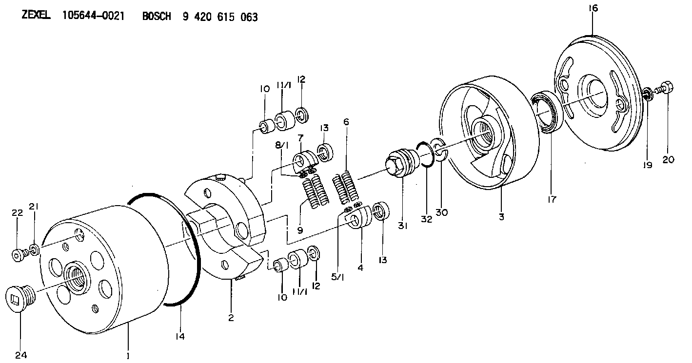
| 1. | [1] | 156400-0620 | TIMING-DEVICE HOUSING |
| 2. | [2] | 156405-0420 | FLYWEIGHT |
| 3. | [1] | 156402-0920 | FLANGE BUSHING |
| 4. | [2] | 156410-0300 | SLOTTED WASHER |
| 5/1. | [0] | 029310-6220 | SHIM D11.5&6.5T0.10 |
| 5/1. | [0] | 029310-6230 | SHIM D11.5&6.5T0.20 |
| 5/1. | [0] | 029310-6240 | SHIM D11.5&6.5T0.25 |
| 5/1. | [0] | 029310-6250 | SHIM D11.5&6.5T1.00 |
| 5/1. | [0] | 029310-6370 | SHIM D11.5&6.5T0.30 |
| 5/1. | [0] | 029310-6380 | SHIM D11.5&6.5T0.40 |
| 5/1. | [0] | 029310-6390 | SHIM D11.5&6.5T0.50 |
| 5/1. | [0] | 029310-6400 | SHIM D11.5&6.5T0.60 |
| 5/1. | [0] | 029310-6410 | SHIM D11.5&6.5T0.70 |
| 5/1. | [0] | 029310-6420 | SHIM D11.5&6.5T0.80 |
| 5/1. | [0] | 029310-6430 | SHIM D11.5&6.5T0.90 |
| 5/1. | [0] | 139406-0500 | SHIM D11.5&6.5T1.5 |
| 5/1. | [0] | 139406-0600 | SHIM D11.5&6.5T2.0 |
| 6. | [2] | 156411-2700 | COMPRESSION SPRING |
| 7. | [2] | 156410-0300 | SLOTTED WASHER |
| 8/1. | [0] | 029310-6220 | SHIM D11.5&6.5T0.10 |
| 8/1. | [0] | 029310-6230 | SHIM D11.5&6.5T0.20 |
| 8/1. | [0] | 029310-6240 | SHIM D11.5&6.5T0.25 |
| 8/1. | [0] | 029310-6250 | SHIM D11.5&6.5T1.00 |
| 8/1. | [0] | 029310-6370 | SHIM D11.5&6.5T0.30 |
| 8/1. | [0] | 029310-6380 | SHIM D11.5&6.5T0.40 |
| 8/1. | [0] | 029310-6390 | SHIM D11.5&6.5T0.50 |
| 8/1. | [0] | 029310-6400 | SHIM D11.5&6.5T0.60 |
| 8/1. | [0] | 029310-6410 | SHIM D11.5&6.5T0.70 |
| 8/1. | [0] | 029310-6420 | SHIM D11.5&6.5T0.80 |
| 8/1. | [0] | 029310-6430 | SHIM D11.5&6.5T0.90 |
| 8/1. | [0] | 139406-0500 | SHIM D11.5&6.5T1.5 |
| 8/1. | [0] | 139406-0600 | SHIM D11.5&6.5T2.0 |
| 9. | [2] | 156411-2700 | COMPRESSION SPRING |
| 10. | [2] | 156412-0100 | BUSHING |
| 10. | [2] | 156412-0100 | BUSHING |
| 11/1. | [2] | 156413-0600 | ROLLER D18.00 |
| 11/1. | [2] | 156413-0600 | ROLLER D18.00 |
| 11/1. | [2] | 156413-0700 | ROLLER D17.90 |
| 11/1. | [2] | 156413-0800 | ROLLER D18.10 |
| 11/1. | [2] | 156413-0900 | ROLLER D18.20 |
| 12. | [2] | 029301-0420 | PLAIN WASHER |
| 12. | [2] | 029301-0420 | PLAIN WASHER |
| 13. | [2] | 156417-0000 | RETAINER |
| 13. | [2] | 156417-0000 | RETAINER |
| 14. | [1] | 156415-0101 | O-RING |
| 16. | [1] | 156408-0100 | COVER |
| 17. | [1] | 156409-0000 | PACKING RING |
| 19. | [2] | 029341-0130 | GASKET |
| 20. | [2] | 029005-8080 | BLEEDER SCREW |
| 21. | [1] | 029331-0190 | GASKET |
| 22. | [1] | 156316-0000 | CAPSULE |
| 24. | [1] | 156314-0301 | CAP |
| 30. | [1] | 029321-4030 | LOCKING WASHER |
| 31. | [1] | 131325-2201 | UNION NUT |
| 32. | [1] | 029632-4060 | O-RING |
Include in #1:
101601-4740
as AUTOM. ADVANCE MECHANIS
Cross reference number
Zexel num
Bosch num
Firm num
Name
105644-0021
1157401020 ISUZU
AUTOM. ADVANCE MECHANISM
K 14KE AUTOMATIC TIMER TIMER SAD(Z) TIMER
K 14KE AUTOMATIC TIMER TIMER SAD(Z) TIMER
Information:
preparatory steps: a) remove timing gear coverb) remove fuel injection pump housing and governorc) remove fuel transfer pump 1. Disconnect the accessory drive oil supply line (1) and the fuel drain line (2). Remove the fuel priming pump.2. Remove the accessory drive shaft gear retaining nut, washer, and sleeve. 3. Using tool (A), remove the accessory drive gear. 4. Remove four retaining bolts (3), two locks and retainer (4).5. Remove the accessory drive housing.6. Remove the accessory drive shaft and bearing as a unit from the housing. 7. Using tool (B), remove bearing (5).Install Accessory Drive Shaft
1. Heat the accessory drive shaft bearing to 300°F (149°C) and install the bearing on the shaft. 2. Install the accessory drive shaft and bearing (1) in the housing.3. Install the accessory drive housing. 4. Install the retainer, locks and retaining bolts.5. Locate top center (TC) compression stroke for No. 1 piston. See LOCATING TOP CENTER COMPRESSION POSITION FOR No. 1 PISTON in TESTING AND ADJUSTING. 6. Rotate the accessory drive shaft until tool (A) can be installed. 7. Install the accessory drive shaft sleeve, drive gear, conical washer and nut. Install the conical washer on the drive shaft with the O.D. in contact with the gear. Tighten the retaining nut (2) to 100 10 lb. ft. (13,8 1,4 mkg).8. Connect the fuel drain line and the oil supply line. Install the fuel priming pump.concluding steps: a) install fuel transfer pumpb) install fuel injection pump housing and governorc) install timing gear cover
1. Heat the accessory drive shaft bearing to 300°F (149°C) and install the bearing on the shaft. 2. Install the accessory drive shaft and bearing (1) in the housing.3. Install the accessory drive housing. 4. Install the retainer, locks and retaining bolts.5. Locate top center (TC) compression stroke for No. 1 piston. See LOCATING TOP CENTER COMPRESSION POSITION FOR No. 1 PISTON in TESTING AND ADJUSTING. 6. Rotate the accessory drive shaft until tool (A) can be installed. 7. Install the accessory drive shaft sleeve, drive gear, conical washer and nut. Install the conical washer on the drive shaft with the O.D. in contact with the gear. Tighten the retaining nut (2) to 100 10 lb. ft. (13,8 1,4 mkg).8. Connect the fuel drain line and the oil supply line. Install the fuel priming pump.concluding steps: a) install fuel transfer pumpb) install fuel injection pump housing and governorc) install timing gear cover