Information autom. advance mechanism
BOSCH
9 420 615 150
9420615150
ZEXEL
105643-1180
1056431180
MITSUBISHI
ME742220
me742220

Rating:
Scheme ###:
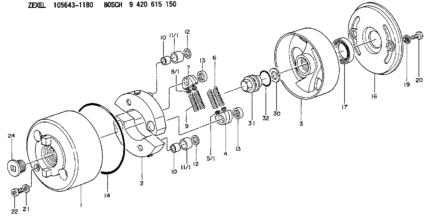
| 1. | [1] | 156400-0720 | TIMING-DEVICE HOUSING |
| 2. | [2] | 156405-2320 | FLYWEIGHT |
| 3. | [1] | 156423-2120 | FLANGE BUSHING |
| 4. | [2] | 156410-0300 | SLOTTED WASHER |
| 5/1. | [0] | 029310-6220 | SHIM D11.5&6.5T0.10 |
| 5/1. | [0] | 029310-6230 | SHIM D11.5&6.5T0.20 |
| 5/1. | [0] | 029310-6240 | SHIM D11.5&6.5T0.25 |
| 5/1. | [0] | 029310-6250 | SHIM D11.5&6.5T1.00 |
| 5/1. | [0] | 029310-6370 | SHIM D11.5&6.5T0.30 |
| 5/1. | [0] | 029310-6380 | SHIM D11.5&6.5T0.40 |
| 5/1. | [0] | 029310-6390 | SHIM D11.5&6.5T0.50 |
| 5/1. | [0] | 029310-6400 | SHIM D11.5&6.5T0.60 |
| 5/1. | [0] | 029310-6410 | SHIM D11.5&6.5T0.70 |
| 5/1. | [0] | 029310-6420 | SHIM D11.5&6.5T0.80 |
| 5/1. | [0] | 029310-6430 | SHIM D11.5&6.5T0.90 |
| 5/1. | [0] | 139406-0500 | SHIM D11.5&6.5T1.5 |
| 5/1. | [0] | 139406-0600 | SHIM D11.5&6.5T2.0 |
| 6. | [2] | 156421-5200 | COMPRESSION SPRING |
| 7. | [2] | 156410-0300 | SLOTTED WASHER |
| 8/1. | [0] | 029310-6220 | SHIM D11.5&6.5T0.10 |
| 8/1. | [0] | 029310-6230 | SHIM D11.5&6.5T0.20 |
| 8/1. | [0] | 029310-6240 | SHIM D11.5&6.5T0.25 |
| 8/1. | [0] | 029310-6250 | SHIM D11.5&6.5T1.00 |
| 8/1. | [0] | 029310-6370 | SHIM D11.5&6.5T0.30 |
| 8/1. | [0] | 029310-6380 | SHIM D11.5&6.5T0.40 |
| 8/1. | [0] | 029310-6390 | SHIM D11.5&6.5T0.50 |
| 8/1. | [0] | 029310-6400 | SHIM D11.5&6.5T0.60 |
| 8/1. | [0] | 029310-6410 | SHIM D11.5&6.5T0.70 |
| 8/1. | [0] | 029310-6420 | SHIM D11.5&6.5T0.80 |
| 8/1. | [0] | 029310-6430 | SHIM D11.5&6.5T0.90 |
| 8/1. | [0] | 139406-0500 | SHIM D11.5&6.5T1.5 |
| 8/1. | [0] | 139406-0600 | SHIM D11.5&6.5T2.0 |
| 9. | [2] | 156421-5200 | COMPRESSION SPRING |
| 10. | [2] | 156412-0100 | BUSHING |
| 10. | [2] | 156412-0100 | BUSHING |
| 11/1. | [1] | 156413-0600 | ROLLER D18.00 |
| 11/1. | [1] | 156413-0700 | ROLLER D17.90 |
| 11/1. | [1] | 156413-0800 | ROLLER D18.10 |
| 11/1. | [1] | 156413-0900 | ROLLER D18.20 |
| 11/1. | [1] | 156413-0900 | ROLLER D18.20 |
| 12. | [2] | 029301-0420 | PLAIN WASHER |
| 12. | [2] | 029301-0420 | PLAIN WASHER |
| 13. | [2] | 156417-0000 | RETAINER |
| 13. | [2] | 156417-0000 | RETAINER |
| 14. | [1] | 156415-0001 | O-RING |
| 16. | [1] | 156408-0100 | COVER |
| 17. | [1] | 156409-0000 | PACKING RING |
| 19. | [2] | 029341-0130 | GASKET |
| 20. | [2] | 029005-8080 | BLEEDER SCREW M8P1.25L15 |
| 21. | [1] | 029331-0190 | GASKET D14&10.2T1 |
| 22. | [1] | 156316-0000 | CAPSULE |
| 24. | [1] | 156314-0301 | CAP |
| 30. | [1] | 029321-4030 | LOCKING WASHER |
| 31. | [1] | 131325-2201 | UNION NUT |
| 32. | [1] | 029632-4060 | O-RING |
Include in #1:
101608-1560
as AUTOM. ADVANCE MECHANIS
Cross reference number
Zexel num
Bosch num
Firm num
Name
Information:
EXHAUST MANIFOLD
1. Locks (four each side). 2. Retaining bolts (eight each side). 3. Exhaust manifold (one each side).Install Exhaust Manifold
1. Clean the exhaust manifold gasket mounting surfaces.2. Position the gasket and exhaust manifold on the engine and install the retaining bolts with locks. Tighten retaining bolts to 32 5 lb. ft. (4.4 0.7 mkg). Bend tabs on locks over flats of retaining bolt heads. Lock tabs must be bent over flats of retaining bolt heads. If necessary to align flats, tighten bolts a maximum additional turn of 30°. Do not loosen bolts to align flats.Disassemble Crankcase Ventilation Valve
1. Remove screws (2) that hold cover (3) on housing (1).
VENTILATION VALVE
1. Housing. 2. Screws (seven). 3. Cover.2. Remove cover (3) and spring (4).
REMOVING COVER
1. Housing. 3. Cover. 4. Spring.3. Remove the piston, sleeve (8), retainer (9), and diaphragm (7) from housing (1) as a unit. Remove inner sleeve (6) and gasket (5) from housing (1).
DISASSEMBLING VALVE
1. Housing. 5. Gasket. 6. Inner sleeve. 7. Diaphragm. 8. Sleeve. 9. Retainer.4. Remove nut (12), washer (13), spacer (11), piston (10), diaphragm (7), and the retainer from sleeve (8).
REMOVING DIAPHRAGM
7. Diaphragm. 8. Sleeve. 10. Piston. 11. Spacer. 12. Nut. 13. Washer.Assemble Crankcase Ventilation Valve
1. Put 5H2471 Gasket Cement on both sides of gasket (5) and install the gasket on housing (1). Install inner sleeve (6) in housing (1).2. Inspect diaphragm (7) for damage. Put piston (10) against side of diaphragm (7) that is stamped "piston side" and put retainer (9) in diaphragm (7).
INSTALLING INNER SLEEVE
1. Housing. 5. Gasket. 6. Inner sleeve.
ASSEMBLING DIAPHRAGM
7. Diaphragm. 9. Retainer. 10. Piston.3. Put the screw through sleeve (8), retainer (9), diaphragm (7), and piston (10). Put spacer (11), washer (13), and nut (12) on the screw and tighten the nut.
ASSEMBLING DIAPHRAGM
7. Diaphragm. 8. Sleeve. 10. Piston. 11. Spacer. 12. Nut. 13. Washer.4. Put 5H2471 Gasket Cement on both sides of the diaphragm (7) to prevent it from distorting and tearing during assembly. Install the assembled diaphragm unit in the inner sleeve (6) and housing (1).
INSTALLING DIAPHRAGM
1. Housing. 5. Gasket. 6. Inner sleeve. 7. Diaphragm. 8. Sleeve. 9. Retainer.5. With the diaphragm unit installed, put spring (4) on the spacer and install cover (3) being sure spring (4) goes over plug (14).
INSTALLING COVER
1. Housing. 3. Cover. 4. Spring. 14. Plug.6. Put screws (2) in housing (1) and tighten the screws.
COVER INSTALLED
1. Housing. 2. Screws (seven). 3. Cover.