Information autom. advance mechanism
BOSCH
9 420 615 376
9420615376
ZEXEL
105643-1140
1056431140
ISUZU
1157404920
1157404920

Rating:
Scheme ###:
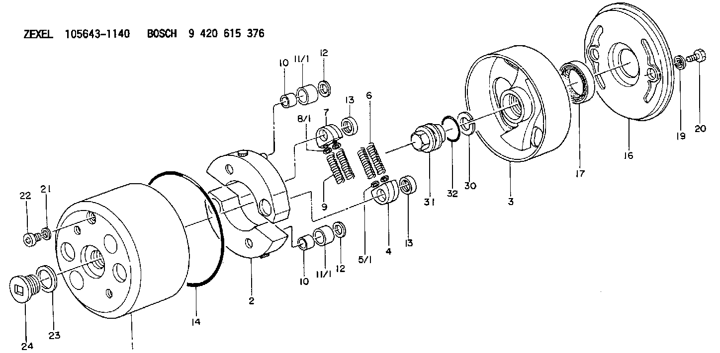
| 1. | [1] | 156400-0820 | TIMING-DEVICE HOUSING |
| 2. | [2] | 156405-6320 | FLYWEIGHT |
| 3. | [1] | 156423-1820 | FLANGE BUSHING |
| 4. | [2] | 156410-0300 | SLOTTED WASHER |
| 5/1. | [0] | 029310-6220 | SHIM D11.5&6.5T0.10 |
| 5/1. | [0] | 029310-6230 | SHIM D11.5&6.5T0.20 |
| 5/1. | [0] | 029310-6240 | SHIM D11.5&6.5T0.25 |
| 5/1. | [0] | 029310-6250 | SHIM D11.5&6.5T1.00 |
| 5/1. | [0] | 029310-6370 | SHIM D11.5&6.5T0.30 |
| 5/1. | [0] | 029310-6380 | SHIM D11.5&6.5T0.40 |
| 5/1. | [0] | 029310-6390 | SHIM D11.5&6.5T0.50 |
| 5/1. | [0] | 029310-6400 | SHIM D11.5&6.5T0.60 |
| 5/1. | [0] | 029310-6410 | SHIM D11.5&6.5T0.70 |
| 5/1. | [0] | 029310-6420 | SHIM D11.5&6.5T0.80 |
| 5/1. | [0] | 029310-6430 | SHIM D11.5&6.5T0.90 |
| 5/1. | [0] | 139406-0500 | SHIM D11.5&6.5T1.5 |
| 5/1. | [0] | 139406-0600 | SHIM D11.5&6.5T2.0 |
| 6. | [2] | 156421-9900 | COMPRESSION SPRING |
| 7. | [2] | 156410-0300 | SLOTTED WASHER |
| 8/1. | [0] | 029310-6220 | SHIM D11.5&6.5T0.10 |
| 8/1. | [0] | 029310-6230 | SHIM D11.5&6.5T0.20 |
| 8/1. | [0] | 029310-6240 | SHIM D11.5&6.5T0.25 |
| 8/1. | [0] | 029310-6250 | SHIM D11.5&6.5T1.00 |
| 8/1. | [0] | 029310-6370 | SHIM D11.5&6.5T0.30 |
| 8/1. | [0] | 029310-6380 | SHIM D11.5&6.5T0.40 |
| 8/1. | [0] | 029310-6390 | SHIM D11.5&6.5T0.50 |
| 8/1. | [0] | 029310-6400 | SHIM D11.5&6.5T0.60 |
| 8/1. | [0] | 029310-6410 | SHIM D11.5&6.5T0.70 |
| 8/1. | [0] | 029310-6420 | SHIM D11.5&6.5T0.80 |
| 8/1. | [0] | 029310-6430 | SHIM D11.5&6.5T0.90 |
| 8/1. | [0] | 139406-0500 | SHIM D11.5&6.5T1.5 |
| 8/1. | [0] | 139406-0600 | SHIM D11.5&6.5T2.0 |
| 9. | [2] | 156421-9900 | COMPRESSION SPRING |
| 10. | [2] | 156412-0100 | BUSHING |
| 10. | [2] | 156412-0100 | BUSHING |
| 11/1. | [1] | 156413-0600 | ROLLER D18.00 |
| 11/1. | [1] | 156413-0700 | ROLLER D17.90 |
| 11/1. | [1] | 156413-0800 | ROLLER D18.10 |
| 11/1. | [1] | 156413-0900 | ROLLER D18.20 |
| 11/1. | [1] | 156413-0900 | ROLLER D18.20 |
| 12. | [2] | 029301-0420 | PLAIN WASHER |
| 12. | [2] | 029301-0420 | PLAIN WASHER |
| 13. | [2] | 156417-0000 | RETAINER |
| 13. | [2] | 156417-0000 | RETAINER |
| 14. | [1] | 156415-0101 | O-RING |
| 16. | [1] | 156408-0100 | COVER |
| 17. | [1] | 156409-0100 | PACKING RING |
| 19. | [2] | 139508-0000 | GASKET D13.2&8.2T1 |
| 20. | [2] | 029005-8080 | BLEEDER SCREW M8P1.25L15 |
| 21. | [1] | 139510-0000 | GASKET D15.2&10.2T1.0 |
| 22. | [1] | 156419-0600 | CAPSULE |
| 23. | [1] | 156419-0300 | GASKET |
| 24. | [1] | 156419-0500 | CAP |
| 30. | [1] | 029321-4030 | LOCKING WASHER |
| 31. | [1] | 131325-2201 | UNION NUT |
| 32. | [1] | 156415-0200 | O-RING |
Include in #1:
101603-8571
as AUTOM. ADVANCE MECHANIS
Cross reference number
Zexel num
Bosch num
Firm num
Name
105643-1140
1157404920 ISUZU
AUTOM. ADVANCE MECHANISM
K 14KE AUTOMATIC TIMER TIMER SAD(Z) TIMER
K 14KE AUTOMATIC TIMER TIMER SAD(Z) TIMER
Information:
TIMING PIN HOLE PLUG (Typical Example)
1. Plug.2. Rotate the crankshaft CLOCKWISE (as viewed from front of engine) until the timing pin drops into the timing slot in the fuel injection pump camshaft.3. Disconnect wire (2) from fuel shut off solenoid.4. Remove the tachometer drive adapter housing (3).
WIRE AND HOUSING (Typical Example)
2. Wire. 3. Tachometer drive adapter housing.5. Use ratchet (4) and socket (5) to remove the tachometer drive adapter shaft.
REMOVING SHAFT
4. 8H8572 Ratchet. 5. 9S5031 Deep Well Socket.6. Using puller group (6), thread the 9S8528 Bolt Assembly into the camshaft. Do not force the bolt assembly. It should thread easily. Install the 9S8527 Bolt by threading it into the gear carrier or adapter. Then tighten the 9S8527 Bolt with a wrench until the gear carrier or adapter "pops" loose. Remove the 9S8520 Puller Group.
LOOSENING CAMSHAFT DRIVE GEAR
6. 9S8520 Puller Group.7. Remove the plug from the timing hole (8) in the front cover and insert bolt (7). The cover retaining bolt from hole (9) may be used.8. Rotate crankshaft CLOCKWISE (as viewed from front of engine) until bolt (7) threads into the timing gear and is centered in timing hole (8). With timing pin in slot in fuel pump camshaft and the bolt (7) through the front cover and threaded into the timing gear, the fuel injection pump camshaft is timed to the engine.
INSTALLING BOLT
7. 1D4539 Bolt [5/16 in. - 18 NC, 2.5 in. (63.5 mm) long]. 8. Timing hole. 9. Hole.9. Remove the fuel injection pump housing retaining bolts (10).
RETAINING BOLTS (Typical Example)
10. Retaining bolts (three).
REMOVING HOUSING (Typical Example)10. Attach a hoist and remove the fuel injection pump housing and governor as a unit, the weight is approx. 55 lbs. (23 kg).Install Fuel Injection Pump Housing and Governor
1. Attach a hoist and install the fuel injection pump housing and governor as a unit. Install the fuel injection pump housing retaining bolts.2. Install the tachometer drive adapter shaft and tighten shaft retaining nut to 32 2 lb. ft. (4.4 0.3 mkg).3. To check timing remove the timing pin and the bolt. Rotate the crankshaft two revolutions CLOCKWISE (as viewed from front of engine) and install the timing pin and bolt back in place. If the timing pin or bolt can not be installed, the fuel injection pump camshaft must be retimed.4. Remove the bolt (7) from the timing gear and install in hole (9). Install the plug into timing hole (8).5. Remove the timing pin from the timing slot in the fuel injection pump camshaft and install the plug in the timing hole.6. Install the tachometer drive adapter housing. Connect the wire to the fuel shut off solenoid.