Information autom. advance mechanism
BOSCH
9 420 615 620
9420615620
ZEXEL
105643-0900
1056430900
MITSUBISHI
ME731698
me731698

Rating:
Scheme ###:
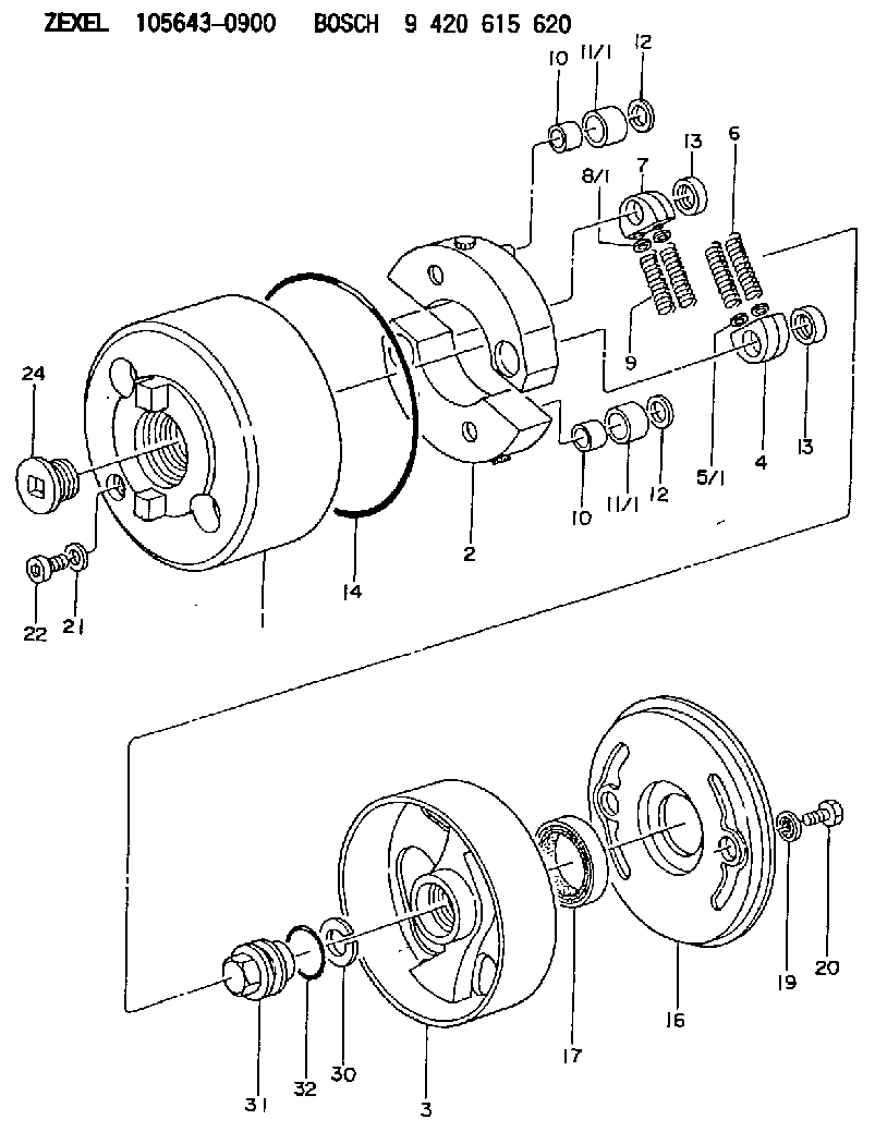
| 1. | [1] | 156400-0720 | TIMING-DEVICE HOUSING |
| 2. | [2] | 156405-2220 | FLYWEIGHT |
| 3. | [1] | 156402-9820 | FLANGE BUSHING |
| 4. | [2] | 156410-0300 | SLOTTED WASHER |
| 5/1. | [0] | 029310-6220 | SHIM D11.5&6.5T0.10 |
| 5/1. | [0] | 029310-6230 | SHIM D11.5&6.5T0.20 |
| 5/1. | [0] | 029310-6240 | SHIM D11.5&6.5T0.25 |
| 5/1. | [0] | 029310-6250 | SHIM D11.5&6.5T1.00 |
| 5/1. | [0] | 029310-6370 | SHIM D11.5&6.5T0.30 |
| 5/1. | [0] | 029310-6380 | SHIM D11.5&6.5T0.40 |
| 5/1. | [0] | 029310-6390 | SHIM D11.5&6.5T0.50 |
| 5/1. | [0] | 029310-6400 | SHIM D11.5&6.5T0.60 |
| 5/1. | [0] | 029310-6410 | SHIM D11.5&6.5T0.70 |
| 5/1. | [0] | 029310-6420 | SHIM D11.5&6.5T0.80 |
| 5/1. | [0] | 029310-6430 | SHIM D11.5&6.5T0.90 |
| 5/1. | [0] | 139406-0500 | SHIM D11.5&6.5T1.5 |
| 5/1. | [0] | 139406-0600 | SHIM D11.5&6.5T2.0 |
| 6. | [2] | 156421-7600 | COMPRESSION SPRING |
| 7. | [2] | 156410-0300 | SLOTTED WASHER |
| 8/1. | [0] | 029310-6220 | SHIM D11.5&6.5T0.10 |
| 8/1. | [0] | 029310-6230 | SHIM D11.5&6.5T0.20 |
| 8/1. | [0] | 029310-6240 | SHIM D11.5&6.5T0.25 |
| 8/1. | [0] | 029310-6250 | SHIM D11.5&6.5T1.00 |
| 8/1. | [0] | 029310-6370 | SHIM D11.5&6.5T0.30 |
| 8/1. | [0] | 029310-6380 | SHIM D11.5&6.5T0.40 |
| 8/1. | [0] | 029310-6390 | SHIM D11.5&6.5T0.50 |
| 8/1. | [0] | 029310-6400 | SHIM D11.5&6.5T0.60 |
| 8/1. | [0] | 029310-6410 | SHIM D11.5&6.5T0.70 |
| 8/1. | [0] | 029310-6420 | SHIM D11.5&6.5T0.80 |
| 8/1. | [0] | 029310-6430 | SHIM D11.5&6.5T0.90 |
| 8/1. | [0] | 139406-0500 | SHIM D11.5&6.5T1.5 |
| 8/1. | [0] | 139406-0600 | SHIM D11.5&6.5T2.0 |
| 9. | [2] | 156421-7600 | COMPRESSION SPRING |
| 10. | [2] | 156412-0100 | BUSHING |
| 10. | [2] | 156412-0100 | BUSHING |
| 11/1. | [1] | 156413-0600 | ROLLER D18.00 |
| 11/1. | [1] | 156413-0700 | ROLLER D17.90 |
| 11/1. | [1] | 156413-0800 | ROLLER D18.10 |
| 11/1. | [1] | 156413-0900 | ROLLER D18.20 |
| 11/1. | [1] | 156413-0900 | ROLLER D18.20 |
| 12. | [2] | 029301-0420 | PLAIN WASHER |
| 12. | [2] | 029301-0420 | PLAIN WASHER |
| 13. | [2] | 156417-0000 | RETAINER |
| 13. | [2] | 156417-0000 | RETAINER |
| 14. | [1] | 156415-0001 | O-RING |
| 16. | [1] | 156408-0100 | COVER |
| 17. | [1] | 156409-0000 | PACKING RING |
| 19. | [2] | 029341-0130 | GASKET |
| 20. | [2] | 029005-8080 | BLEEDER SCREW M8P1.25L15 |
| 21. | [1] | 029331-0190 | GASKET D14&10.2T1 |
| 22. | [1] | 156316-0000 | CAPSULE |
| 24. | [1] | 156314-0301 | CAP |
| 30. | [1] | 029321-4030 | LOCKING WASHER |
| 31. | [1] | 131325-2201 | UNION NUT |
| 32. | [1] | 029632-4060 | O-RING |
Include in #1:
101606-6982
as AUTOM. ADVANCE MECHANIS
Cross reference number
Zexel num
Bosch num
Firm num
Name
105643-0900
ME731698 MITSUBISHI
AUTOM. ADVANCE MECHANISM
K 14KE AUTOMATIC TIMER TIMER SAD(Z) TIMER
K 14KE AUTOMATIC TIMER TIMER SAD(Z) TIMER
Information:
Cylinder Head Removal And Installation
Refer to SERVICE GUIDE for Preliminary Information.
1-Water pipe. 2-Fan and pulley mounting bracket assembly. 3-Water bypass line. 4-Air compressor water return line.
5-Turbocharger-to-inlet manifold air pipe. 6-Turbocharger lubrication oil supply line. 7-Turbocharger oil drain line. 8-Exhaust elbow. 9-Turbocharger. 10-Fuel lines (six). 11-Valve cover. 12-Cylinder head.Cylinder Head Disassembly And Assembly
Refer to SERVICE GUIDE for Preliminary Information.5F8353 Wrench5S1330 Valve Spring Compressor Group7S8858 Valve Guide Driver Bushing7S8859 Valve Guide DriverFT192 Driver9M3710 Anti-Seize Compound8S3080 Tool Group9S3084 Extractor Head9S3087 Extractor HeadApply 9M3710 Anti-Seize Compound to threads. Tighten all head bolts (1, 2 and 3) in Step sequence shown. Use gaskets (6) to position precombustion chambers (4) to prevent wiring interference. Install thinnest gasket (6) first. Install precombustion chamber and tighten to specified torque. If the glow plug opening is not positioned in the "go" range, remove the chamber and replace gasket with that called for in the diagram.4 Use 5F8353 Wrench to remove and install chamber. Coat threads with 9M3710 Anti-Seize Compound.5 Coat seal and mating surface in bore with liquid soap.7 Align opening in water director with "V" mark on head.8 Gasket to be clean and dry at installation.9, 10 Tool required: 5S1330 Valve Spring Compressor Group. Assemble spring with painted end up.11 Tool required to remove valve guide: 7S8859 Valve Guide Driver. Tools required to install valve guide: 7S8859 Valve Guide Driver, 7S8858 Valve Guide Driver Bushing.12 Valve seat inserts can be removed and new inserts installed in the cylinder heads. Tools required to remove inserts: 9S3080 Tool Group, 9S3084 Extractor Head, 9S3087 Extractor Head.13 Tool required to install bearing: FT192 Driver. Align hole in bearing with hole in rocker arm.