Information autom. advance mechanism
BOSCH
9 420 615 346
9420615346
ZEXEL
105643-0730
1056430730
MITSUBISHI
ME727898
me727898
Rating:
Compare Prices: .
As an associate, we earn commssions on qualifying purchases through the links below

$3,364.59
24 Apr 2019
Parts Expr: Parts Express
TIMER ASSEMBLY FOR MITSUBISHI: 1056430730
MITSUBISHI || All Brand new & rebuilt items comes with 1 year warranty. || TIMER ASSEMBLY FOR MITSUBISHI: Â FORKLIFT. MB1056430730 MB1056430730 MITSUBISHI 1056430730 MB 1056430730 1056430730 MITSUBISHI1056430730 Â Â Â Â Â Â THIS PART IS ALSO LISTED UNDER THE FOLLOWING PART NUMBERS:
MITSUBISHI || All Brand new & rebuilt items comes with 1 year warranty. || TIMER ASSEMBLY FOR MITSUBISHI: Â FORKLIFT. MB1056430730 MB1056430730 MITSUBISHI 1056430730 MB 1056430730 1056430730 MITSUBISHI1056430730 Â Â Â Â Â Â THIS PART IS ALSO LISTED UNDER THE FOLLOWING PART NUMBERS:
Scheme ###:
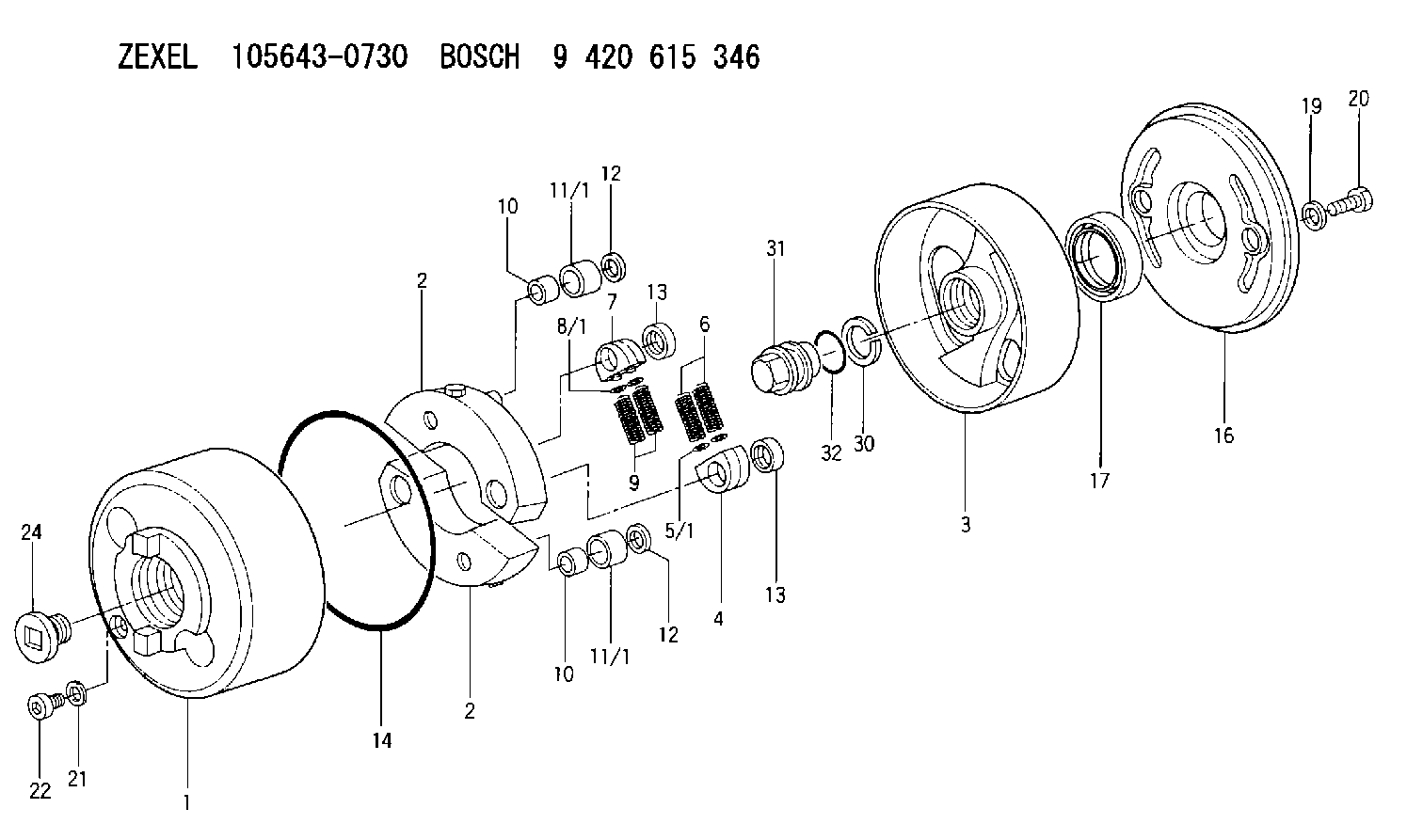
| 1. | [1] | 156400-0720 | TIMING-DEVICE HOUSING |
| 2. | [2] | 156405-2220 | FLYWEIGHT |
| 2. | [2] | 156405-2220 | FLYWEIGHT |
| 3. | [1] | 156402-7820 | FLANGE BUSHING |
| 4. | [2] | 156410-0300 | SLOTTED WASHER |
| 5/1. | [0] | 029310-6220 | SHIM D11.5&6.5T0.10 |
| 5/1. | [0] | 029310-6230 | SHIM D11.5&6.5T0.20 |
| 5/1. | [0] | 029310-6240 | SHIM D11.5&6.5T0.25 |
| 5/1. | [0] | 029310-6250 | SHIM D11.5&6.5T1.00 |
| 5/1. | [0] | 029310-6370 | SHIM D11.5&6.5T0.30 |
| 5/1. | [0] | 029310-6380 | SHIM D11.5&6.5T0.40 |
| 5/1. | [0] | 029310-6390 | SHIM D11.5&6.5T0.50 |
| 5/1. | [0] | 029310-6400 | SHIM D11.5&6.5T0.60 |
| 5/1. | [0] | 029310-6410 | SHIM D11.5&6.5T0.70 |
| 5/1. | [0] | 029310-6420 | SHIM D11.5&6.5T0.80 |
| 5/1. | [0] | 029310-6430 | SHIM D11.5&6.5T0.90 |
| 5/1. | [0] | 139406-0500 | SHIM D11.5&6.5T1.5 |
| 5/1. | [0] | 139406-0600 | SHIM D11.5&6.5T2.0 |
| 6. | [2] | 156421-6200 | COMPRESSION SPRING |
| 7. | [2] | 156410-0300 | SLOTTED WASHER |
| 8/1. | [0] | 029310-6220 | SHIM D11.5&6.5T0.10 |
| 8/1. | [0] | 029310-6230 | SHIM D11.5&6.5T0.20 |
| 8/1. | [0] | 029310-6240 | SHIM D11.5&6.5T0.25 |
| 8/1. | [0] | 029310-6250 | SHIM D11.5&6.5T1.00 |
| 8/1. | [0] | 029310-6370 | SHIM D11.5&6.5T0.30 |
| 8/1. | [0] | 029310-6380 | SHIM D11.5&6.5T0.40 |
| 8/1. | [0] | 029310-6390 | SHIM D11.5&6.5T0.50 |
| 8/1. | [0] | 029310-6400 | SHIM D11.5&6.5T0.60 |
| 8/1. | [0] | 029310-6410 | SHIM D11.5&6.5T0.70 |
| 8/1. | [0] | 029310-6420 | SHIM D11.5&6.5T0.80 |
| 8/1. | [0] | 029310-6430 | SHIM D11.5&6.5T0.90 |
| 8/1. | [0] | 139406-0500 | SHIM D11.5&6.5T1.5 |
| 8/1. | [0] | 139406-0600 | SHIM D11.5&6.5T2.0 |
| 9. | [2] | 156421-6200 | COMPRESSION SPRING |
| 10. | [2] | 156412-0100 | BUSHING |
| 10. | [2] | 156412-0100 | BUSHING |
| 11/1. | [1] | 156413-0600 | ROLLER D18.00 |
| 11/1. | [1] | 156413-0700 | ROLLER D17.90 |
| 11/1. | [1] | 156413-0800 | ROLLER D18.10 |
| 11/1. | [1] | 156413-0800 | ROLLER D18.10 |
| 11/1. | [1] | 156413-0900 | ROLLER D18.20 |
| 12. | [2] | 029301-0420 | PLAIN WASHER |
| 12. | [2] | 029301-0420 | PLAIN WASHER |
| 13. | [2] | 156417-0000 | RETAINER |
| 13. | [2] | 156417-0000 | RETAINER |
| 14. | [1] | 156415-0001 | O-RING |
| 16. | [1] | 156408-0100 | COVER |
| 17. | [1] | 156409-0000 | PACKING RING |
| 19. | [2] | 029341-0130 | GASKET |
| 20. | [2] | 029005-8080 | BLEEDER SCREW M8P1.25L15 |
| 21. | [1] | 029331-0190 | GASKET D14&10.2T1 |
| 22. | [1] | 156316-0000 | CAPSULE |
| 24. | [1] | 156314-0301 | CAP |
| 30. | [1] | 029321-4030 | LOCKING WASHER |
| 31. | [1] | 131325-2201 | UNION NUT |
| 32. | [1] | 029632-4060 | O-RING |
Include in #1:
101607-1460
as AUTOM. ADVANCE MECHANIS
Cross reference number
Zexel num
Bosch num
Firm num
Name
105643-0730
ME727898 MITSUBISHI
AUTOM. ADVANCE MECHANISM
K 14KE AUTOMATIC TIMER TIMER SAD(Z) TIMER
K 14KE AUTOMATIC TIMER TIMER SAD(Z) TIMER
Information:
start by: a) remove oil pump1. Check the connecting rods and caps for their identification and location.2. Turn crankshaft until connecting rod caps are in position shown. 3. Remove the nuts (1) and the cap from connecting rod. Remove lower half of bearing from cap.4. Push the connecting rod away from the crankshaft. Remove the upper half of bearing from connecting rod. Install the bearings dry when the clearance checks are made. Put clean engine oil on the bearings for final assembly.5. Install upper half of bearing in connecting rod.6. Pull the connecting rod slowly on to the crankshaft.7. Install lower half of bearing in cap. Be sure the tabs in back of bearings are in the tab grooves of connecting rod and cap.
Do not use an impact wrench to tighten the bolts the additional 120° 5°.
8. Use Plastigage (A) to check bearing clearance.9. Put Plastigage (A) on the bearing.10. Put clean engine oil on threads of rod bolts and seat surfaces of nuts. Be sure the cylinder numbers on the rod cap and rod are the same and are on the same side of the connecting rod. Numbers are on the same side of rod and caps as are the grooves for the bearing tabs. If new rods are installed, put the cylinder number on the rod and cap. Do not turn the crankshaft when Plastigage (A) is in position. 11. Install the rod caps (2). Install the nuts. Tighten each nut to a torque of 60 6 lb. ft. (80 8 N m). Put a mark on the nuts and cap and tighten nuts an extra 120° 5° from the mark. Remove the rod cap. Remove Plastigage (A) and check the bearing clearance. The bearing clearance must be .0028 to .0066 in. (0.071 to 0.168 mm) for new bearings. Maximum clearance with used bearings is .010 in. (0.25 mm).12. Put clean engine oil on lower half of bearing. Install rod cap again. Tighten each nut to 60 6 lb.ft. (80 8 N m). Put a mark on nuts and cap and tighten nuts an extra 120° 5° from mark.13. Do Steps 1 through 12 for remainder of connecting rod bearings.end by:a) install oil pump