Information autom. advance mechanism
BOSCH
9 420 615 678
9420615678
ZEXEL
105643-0610
1056430610
ISUZU
1157403610
1157403610
Rating:
Scheme ###:
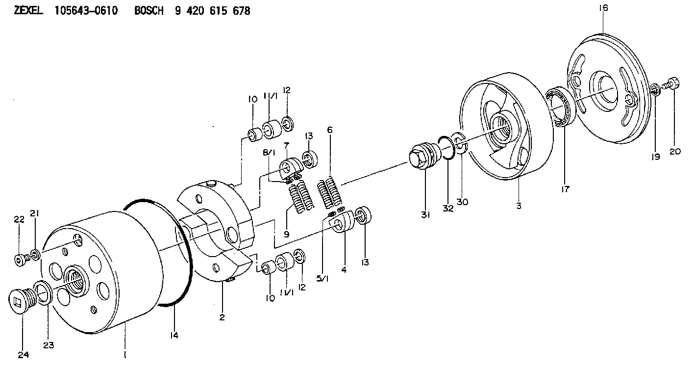
| 1. | [1] | 156400-0820 | TIMING-DEVICE HOUSING |
| 2. | [2] | 156405-2320 | FLYWEIGHT |
| 3. | [1] | 156402-8420 | FLANGE BUSHING |
| 4. | [2] | 156410-0300 | SLOTTED WASHER |
| 5/1. | [0] | 029310-6220 | SHIM D11.5&6.5T0.10 |
| 5/1. | [0] | 029310-6230 | SHIM D11.5&6.5T0.20 |
| 5/1. | [0] | 029310-6240 | SHIM D11.5&6.5T0.25 |
| 5/1. | [0] | 029310-6250 | SHIM D11.5&6.5T1.00 |
| 5/1. | [0] | 029310-6370 | SHIM D11.5&6.5T0.30 |
| 5/1. | [0] | 029310-6380 | SHIM D11.5&6.5T0.40 |
| 5/1. | [0] | 029310-6390 | SHIM D11.5&6.5T0.50 |
| 5/1. | [0] | 029310-6400 | SHIM D11.5&6.5T0.60 |
| 5/1. | [0] | 029310-6410 | SHIM D11.5&6.5T0.70 |
| 5/1. | [0] | 029310-6420 | SHIM D11.5&6.5T0.80 |
| 5/1. | [0] | 029310-6430 | SHIM D11.5&6.5T0.90 |
| 5/1. | [0] | 139406-0500 | SHIM D11.5&6.5T1.5 |
| 5/1. | [0] | 139406-0600 | SHIM D11.5&6.5T2.0 |
| 6. | [2] | 156411-3600 | COMPRESSION SPRING |
| 7. | [2] | 156410-0300 | SLOTTED WASHER |
| 8/1. | [0] | 029310-6220 | SHIM D11.5&6.5T0.10 |
| 8/1. | [0] | 029310-6230 | SHIM D11.5&6.5T0.20 |
| 8/1. | [0] | 029310-6240 | SHIM D11.5&6.5T0.25 |
| 8/1. | [0] | 029310-6250 | SHIM D11.5&6.5T1.00 |
| 8/1. | [0] | 029310-6370 | SHIM D11.5&6.5T0.30 |
| 8/1. | [0] | 029310-6380 | SHIM D11.5&6.5T0.40 |
| 8/1. | [0] | 029310-6390 | SHIM D11.5&6.5T0.50 |
| 8/1. | [0] | 029310-6400 | SHIM D11.5&6.5T0.60 |
| 8/1. | [0] | 029310-6410 | SHIM D11.5&6.5T0.70 |
| 8/1. | [0] | 029310-6420 | SHIM D11.5&6.5T0.80 |
| 8/1. | [0] | 029310-6430 | SHIM D11.5&6.5T0.90 |
| 8/1. | [0] | 139406-0500 | SHIM D11.5&6.5T1.5 |
| 8/1. | [0] | 139406-0600 | SHIM D11.5&6.5T2.0 |
| 9. | [2] | 156411-3600 | COMPRESSION SPRING |
| 10. | [2] | 156412-0100 | BUSHING |
| 10. | [2] | 156412-0100 | BUSHING |
| 11/1. | [1] | 156413-0600 | ROLLER D18.00 |
| 11/1. | [1] | 156413-0700 | ROLLER D17.90 |
| 11/1. | [1] | 156413-0800 | ROLLER D18.10 |
| 11/1. | [1] | 156413-0900 | ROLLER D18.20 |
| 11/1. | [1] | 156413-0900 | ROLLER D18.20 |
| 12. | [2] | 029301-0420 | PLAIN WASHER |
| 12. | [2] | 029301-0420 | PLAIN WASHER |
| 13. | [2] | 156417-0000 | RETAINER |
| 13. | [2] | 156417-0000 | RETAINER |
| 14. | [1] | 156415-0101 | O-RING |
| 16. | [1] | 156408-0100 | COVER |
| 17. | [1] | 156409-0100 | PACKING RING |
| 19. | [2] | 139508-0000 | GASKET D13.2&8.2T1 |
| 20. | [2] | 029005-8080 | BLEEDER SCREW M8P1.25L15 |
| 21. | [1] | 139510-0000 | GASKET D15.2&10.2T1.0 |
| 22. | [1] | 156419-0600 | CAPSULE |
| 23. | [1] | 156419-0300 | GASKET |
| 24. | [1] | 156419-0500 | CAP |
| 30. | [1] | 029321-4030 | LOCKING WASHER |
| 31. | [1] | 131325-2201 | UNION NUT |
| 32. | [1] | 156415-0200 | O-RING |
Include in #1:
101603-7280
as AUTOM. ADVANCE MECHANIS
Cross reference number
Zexel num
Bosch num
Firm num
Name
105643-0610
1157403610 ISUZU
AUTOM. ADVANCE MECHANISM
K 14KE AUTOMATIC TIMER TIMER SAD(Z) TIMER
K 14KE AUTOMATIC TIMER TIMER SAD(Z) TIMER
Information:
start by:a) separation of governor from fuel injection pump housing 1. Remove the ring (3) and pin (1) that hold seat (2). 2. Remove seat (2), bolt (4), washers (6) and spring (5).3. Remove the sleeve and bearing assembly from the cylinder and weight assemblies. 4. Remove ring (7) from sleeve (8).5. Remove bearing (9) and washers (10) from sleeve (8). 6. Remove valve (12) from piston (11). 7. Remove ring (15) that holds the weight assembly to cylinder (16).8. Remove weight assembly (13) from the cylinder.9. Remove piston (11) and sleeve (14) from the cylinder. Remove the O-ring seal from sleeve (14). 10. Remove speed limiter plug (20), spring and plunger from the governor housing (19).11. Remove torque spring assembly (17). 12. Remove bolt (21) and lock that hold lever (22) to shaft (18).13. Remove lever (22) and shaft from the housing.14. Remove the seal from housing (19).15. Remove the bearings and plug from the housing with tooling (A). 16. Remove two bolts (23), lock, lever arm (26) and shaft (25) from idle screw housing (24).17. Remove the two seals, bearings and plug from housing (24) with tooling (A).Assemble Governor
1. Use tooling (A) to install inner seal (3) in idle screw housing (2). Install seal (3) so the lip of the seal is toward bearing (4). Put clean engine oil on the lips of the seals.2. Use tooling (A) to install bearing (1) and the outer seal. Install the outer seal with the lip of the seal toward the outside. Install bearing (4). 3. Install bearing (6) in governor housing (8) to dimension (Y) or .897 .010 in. (22.97 0.25 mm) with tooling (A). Install bearing (5) in the governor housing to dimension (X) or 2.385 .005 in. (60.58 0.13 mm) from bearing (6). Install plug (7) in the governor housing. 4. Use tooling (A) to install the seal in governor housing (8). Install the seal with the lip of the seal toward the inside.5. Install torque spring assembly (9) on the governor housing. Install the lock and bolts that hold it. See RACK SETTING INFORMATION for the correct adjustment of the torque spring assembly. 6. Put lever assembly (11) in position in the governor housing. Install shaft (10) in the housing through the lever. Install the lock and bolt that hold the lever to the shaft. 7. Install speed limiter plunger (14), spring (13) and plug (12) in the governor housing. 8. Install O-ring seal (17) on sleeve (18).9. Install piston (16) and the sleeve in cylinder (15). 10. Put weight assembly (19) on cylinder (15). Install the ring that holds the weight assembly on the cylinder. 11. Install valve (21) in piston (16).12. Install bearing and washers (22) on sleeve (20). Install the ring that holds the washers and bearing on the sleeve.13. Install the sleeve assembly on valve (21). 14. Install bolt (23) in seat (24). Install the washers and spring in the seat.15. Put the seat in position on
1. Use tooling (A) to install inner seal (3) in idle screw housing (2). Install seal (3) so the lip of the seal is toward bearing (4). Put clean engine oil on the lips of the seals.2. Use tooling (A) to install bearing (1) and the outer seal. Install the outer seal with the lip of the seal toward the outside. Install bearing (4). 3. Install bearing (6) in governor housing (8) to dimension (Y) or .897 .010 in. (22.97 0.25 mm) with tooling (A). Install bearing (5) in the governor housing to dimension (X) or 2.385 .005 in. (60.58 0.13 mm) from bearing (6). Install plug (7) in the governor housing. 4. Use tooling (A) to install the seal in governor housing (8). Install the seal with the lip of the seal toward the inside.5. Install torque spring assembly (9) on the governor housing. Install the lock and bolts that hold it. See RACK SETTING INFORMATION for the correct adjustment of the torque spring assembly. 6. Put lever assembly (11) in position in the governor housing. Install shaft (10) in the housing through the lever. Install the lock and bolt that hold the lever to the shaft. 7. Install speed limiter plunger (14), spring (13) and plug (12) in the governor housing. 8. Install O-ring seal (17) on sleeve (18).9. Install piston (16) and the sleeve in cylinder (15). 10. Put weight assembly (19) on cylinder (15). Install the ring that holds the weight assembly on the cylinder. 11. Install valve (21) in piston (16).12. Install bearing and washers (22) on sleeve (20). Install the ring that holds the washers and bearing on the sleeve.13. Install the sleeve assembly on valve (21). 14. Install bolt (23) in seat (24). Install the washers and spring in the seat.15. Put the seat in position on