Information autom. advance mechanism
BOSCH
9 420 616 703
9420616703
ZEXEL
105643-0560
1056430560
MITSUBISHI
ME726498
me726498
Rating:
Scheme ###:
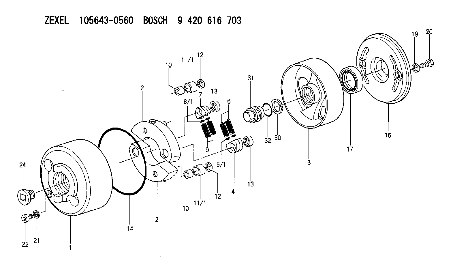
| 1. | [1] | 156400-0720 | TIMING-DEVICE HOUSING |
| 2. | [2] | 156405-8120 | FLYWEIGHT |
| 2. | [2] | 156405-8120 | FLYWEIGHT |
| 3. | [1] | 156402-7820 | FLANGE BUSHING |
| 4. | [2] | 156410-0300 | SLOTTED WASHER |
| 5/1. | [0] | 029310-6220 | SHIM D11.5&6.5T0.10 |
| 5/1. | [0] | 029310-6230 | SHIM D11.5&6.5T0.20 |
| 5/1. | [0] | 029310-6240 | SHIM D11.5&6.5T0.25 |
| 5/1. | [0] | 029310-6250 | SHIM D11.5&6.5T1.00 |
| 5/1. | [0] | 029310-6370 | SHIM D11.5&6.5T0.30 |
| 5/1. | [0] | 029310-6380 | SHIM D11.5&6.5T0.40 |
| 5/1. | [0] | 029310-6390 | SHIM D11.5&6.5T0.50 |
| 5/1. | [0] | 029310-6400 | SHIM D11.5&6.5T0.60 |
| 5/1. | [0] | 029310-6410 | SHIM D11.5&6.5T0.70 |
| 5/1. | [0] | 029310-6420 | SHIM D11.5&6.5T0.80 |
| 5/1. | [0] | 029310-6430 | SHIM D11.5&6.5T0.90 |
| 5/1. | [0] | 139406-0500 | SHIM D11.5&6.5T1.5 |
| 5/1. | [0] | 139406-0600 | SHIM D11.5&6.5T2.0 |
| 6. | [2] | 156411-7500 | COMPRESSION SPRING |
| 7. | [2] | 156410-0300 | SLOTTED WASHER |
| 8/1. | [0] | 029310-6220 | SHIM D11.5&6.5T0.10 |
| 8/1. | [0] | 029310-6230 | SHIM D11.5&6.5T0.20 |
| 8/1. | [0] | 029310-6240 | SHIM D11.5&6.5T0.25 |
| 8/1. | [0] | 029310-6250 | SHIM D11.5&6.5T1.00 |
| 8/1. | [0] | 029310-6370 | SHIM D11.5&6.5T0.30 |
| 8/1. | [0] | 029310-6380 | SHIM D11.5&6.5T0.40 |
| 8/1. | [0] | 029310-6390 | SHIM D11.5&6.5T0.50 |
| 8/1. | [0] | 029310-6400 | SHIM D11.5&6.5T0.60 |
| 8/1. | [0] | 029310-6410 | SHIM D11.5&6.5T0.70 |
| 8/1. | [0] | 029310-6420 | SHIM D11.5&6.5T0.80 |
| 8/1. | [0] | 029310-6430 | SHIM D11.5&6.5T0.90 |
| 8/1. | [0] | 139406-0500 | SHIM D11.5&6.5T1.5 |
| 8/1. | [0] | 139406-0600 | SHIM D11.5&6.5T2.0 |
| 9. | [2] | 156411-7500 | COMPRESSION SPRING |
| 9B. | [2] | 156421-1600 | COMPRESSION SPRING |
| 10. | [2] | 156412-0100 | BUSHING |
| 10. | [2] | 156412-0100 | BUSHING |
| 11/1. | [1] | 156413-0600 | ROLLER D18.00 |
| 11/1. | [1] | 156413-0600 | ROLLER D18.00 |
| 11/1. | [1] | 156413-0700 | ROLLER D17.90 |
| 11/1. | [1] | 156413-0800 | ROLLER D18.10 |
| 11/1. | [1] | 156413-0900 | ROLLER D18.20 |
| 12. | [2] | 029301-0420 | PLAIN WASHER |
| 12. | [2] | 029301-0420 | PLAIN WASHER |
| 13. | [2] | 156417-0000 | RETAINER |
| 13. | [2] | 156417-0000 | RETAINER |
| 14. | [1] | 156415-0001 | O-RING |
| 16. | [1] | 156408-0100 | COVER |
| 17. | [1] | 156409-0200 | PACKING RING |
| 19. | [2] | 156319-0000 | GASKET |
| 20. | [2] | 029005-8080 | BLEEDER SCREW M8P1.25L15 |
| 21. | [1] | 029331-0190 | GASKET D14&10.2T1 |
| 22. | [1] | 156316-0000 | CAPSULE |
| 24. | [1] | 156314-0301 | CAP |
| 30. | [1] | 029321-4030 | LOCKING WASHER |
| 31. | [1] | 131325-2201 | UNION NUT |
| 32. | [1] | 029632-4060 | O-RING |
Include in #1:
101606-6660
as AUTOM. ADVANCE MECHANIS
Cross reference number
Zexel num
Bosch num
Firm num
Name
105643-0560
ME726498 MITSUBISHI
AUTOM. ADVANCE MECHANISM
K 14KE AUTOMATIC TIMER TIMER SAD(Z) TIMER
K 14KE AUTOMATIC TIMER TIMER SAD(Z) TIMER
Information:
start by:a) remove fuel transfer pump 1. Remove bolts (1). Remove cover (2) from the fuel transfer pump. 2. Remove bolt (3). Remove gasket, spring and plunger from under bolt.3. Remove gear (4).4. Remove shaft assembly (5). 5. Remove O-ring seal (7) from body assembly.6. Install a 5/16"-18 NC forged eyebolt (6) in the plug. Remove plug (8) and O-ring seal. Remove the O-ring seal from the plug. 7. Remove valve assembly (9). 8. Remove two lip seals (10) from the body assembly. 9. Remove two bearings (11) from the body assembly with tooling (A).Assemble Fuel Transfer Pump (Later)
1. Install bearings in body (1) with tooling (A). Install bearing on gear end of body to a depth of .03 .02 in. (0.76 0.51 mm) below the surface of the body. Install the bearing on the opposite end of the body even with the body surface. 2. Put 4H5363 Sealant on the outside diameters of the seals. Install the lip seals in the body assembly with tooling (A). Install the first seal with lip toward bearing. Install the lip seal to a depth of .406 .010 (10.31 0.25 mm). Install the second seal with lip away from bearing. Make sure the second lip seal is even with the surface of the body assembly. 3. Install the valve assembly in the body assembly with tooling (A) to a depth of .57 .02 in. (14.5 0.5 mm). 4. Install O-ring seal (3) on the plug. Install a 5/16"-18 NC forged eyebolt (2) in the plug. Put a small amount of clean diesel fuel on the O-ring seal and install plug (4) in the body assembly. Make sure plug is even with the surface of the body.5. Install O-ring seal on the body assembly. 6. Put a small amount of clean diesel fuel on the lip seals. Put tool (B) in position on shaft assembly. Install shaft assembly (5) in the body assembly. 7. Install gear (7).
Do not get liquid gasket material into pump.
8. Put 7M7260 Liquid Gasket Material on the body assembly surface that makes contact with the cover. Install cover (6).9. Shaft assembly must turn by hand after cover is installed. 10. Install plunger (8), spring (9), gasket (11) and plug (10) in body assembly. Tighten plug to a torque of 27 3 lb. ft. (38 4 N m).end by:a) install fuel transfer pump