Information autom. advance mechanism
BOSCH
9 420 615 674
9420615674
ZEXEL
105643-0190
1056430190
ISUZU
1157402020
1157402020
Rating:
Scheme ###:
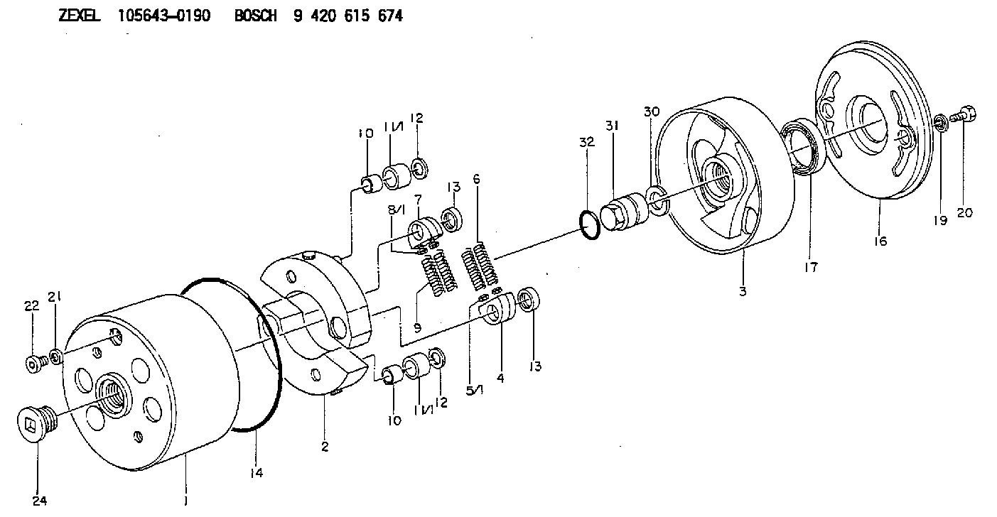
| 1. | [1] | 156400-0620 | TIMING-DEVICE HOUSING |
| 2. | [2] | 156405-6720 | FLYWEIGHT |
| 3. | [1] | 156402-5020 | FLANGE BUSHING |
| 4. | [2] | 156410-0300 | SLOTTED WASHER |
| 5/1. | [0] | 029310-6220 | SHIM D11.5&6.5T0.10 |
| 5/1. | [0] | 029310-6230 | SHIM D11.5&6.5T0.20 |
| 5/1. | [0] | 029310-6240 | SHIM D11.5&6.5T0.25 |
| 5/1. | [0] | 029310-6250 | SHIM D11.5&6.5T1.00 |
| 5/1. | [0] | 029310-6370 | SHIM D11.5&6.5T0.30 |
| 5/1. | [0] | 029310-6380 | SHIM D11.5&6.5T0.40 |
| 5/1. | [0] | 029310-6390 | SHIM D11.5&6.5T0.50 |
| 5/1. | [0] | 029310-6400 | SHIM D11.5&6.5T0.60 |
| 5/1. | [0] | 029310-6410 | SHIM D11.5&6.5T0.70 |
| 5/1. | [0] | 029310-6420 | SHIM D11.5&6.5T0.80 |
| 5/1. | [0] | 029310-6430 | SHIM D11.5&6.5T0.90 |
| 5/1. | [0] | 139406-0500 | SHIM D11.5&6.5T1.5 |
| 5/1. | [0] | 139406-0600 | SHIM D11.5&6.5T2.0 |
| 6. | [2] | 156411-6100 | COMPRESSION SPRING |
| 7. | [2] | 156410-0300 | SLOTTED WASHER |
| 8/1. | [0] | 029310-6220 | SHIM D11.5&6.5T0.10 |
| 8/1. | [0] | 029310-6230 | SHIM D11.5&6.5T0.20 |
| 8/1. | [0] | 029310-6240 | SHIM D11.5&6.5T0.25 |
| 8/1. | [0] | 029310-6250 | SHIM D11.5&6.5T1.00 |
| 8/1. | [0] | 029310-6370 | SHIM D11.5&6.5T0.30 |
| 8/1. | [0] | 029310-6380 | SHIM D11.5&6.5T0.40 |
| 8/1. | [0] | 029310-6390 | SHIM D11.5&6.5T0.50 |
| 8/1. | [0] | 029310-6400 | SHIM D11.5&6.5T0.60 |
| 8/1. | [0] | 029310-6410 | SHIM D11.5&6.5T0.70 |
| 8/1. | [0] | 029310-6420 | SHIM D11.5&6.5T0.80 |
| 8/1. | [0] | 029310-6430 | SHIM D11.5&6.5T0.90 |
| 8/1. | [0] | 139406-0500 | SHIM D11.5&6.5T1.5 |
| 8/1. | [0] | 139406-0600 | SHIM D11.5&6.5T2.0 |
| 9. | [2] | 156411-6100 | COMPRESSION SPRING |
| 10. | [2] | 156412-0100 | BUSHING |
| 10. | [2] | 156412-0100 | BUSHING |
| 11/1. | [1] | 156413-0600 | ROLLER D18.00 |
| 11/1. | [1] | 156413-0600 | ROLLER D18.00 |
| 11/1. | [1] | 156413-0700 | ROLLER D17.90 |
| 11/1. | [1] | 156413-0800 | ROLLER D18.10 |
| 11/1. | [1] | 156413-0900 | ROLLER D18.20 |
| 12. | [2] | 029301-0420 | PLAIN WASHER |
| 12. | [2] | 029301-0420 | PLAIN WASHER |
| 13. | [2] | 156417-0000 | RETAINER |
| 13. | [2] | 156417-0000 | RETAINER |
| 14. | [1] | 156415-0001 | O-RING |
| 16. | [1] | 156408-0100 | COVER |
| 17. | [1] | 156409-0000 | PACKING RING |
| 19. | [2] | 029341-0130 | GASKET |
| 20. | [2] | 029005-8080 | BLEEDER SCREW M8P1.25L15 |
| 21. | [1] | 029331-0190 | GASKET D14&10.2T1 |
| 22. | [1] | 156316-0000 | CAPSULE |
| 24. | [1] | 156314-0301 | CAP |
| 30. | [1] | 029321-4030 | LOCKING WASHER |
| 31. | [1] | 131325-2201 | UNION NUT |
| 32. | [1] | 029632-4060 | O-RING |
Cross reference number
Zexel num
Bosch num
Firm num
Name
105643-0190
1157402020 ISUZU
AUTOM. ADVANCE MECHANISM
K 14KE AUTOMATIC TIMER TIMER SAD(Z) TIMER
K 14KE AUTOMATIC TIMER TIMER SAD(Z) TIMER
Information:
1. Remove all of bolts (1) and bolts (2) and (3).2. Use two 3/8"-16 NC forcing screws and remove stator (4) from the flywheel housing. 3. If necessary remove the lip type seal from stator (4) with a hammer and punch. 4. Remove the six O-ring seals (6) from the flywheel housing.5. Remove rotor (5) from the crankshaft. 6. Remove the seal ring from carrier (8).7. If necessary remove carrier (8) and sleeve (7) from rotor (5). The carrier and sleeve will have damage after removal. Use new parts for replacement.Install BrakeSaver
1. If the carrier and sleeve were removed from the rotor, heat the new parts to a maximum temperature of 300° F (149° C). 2. Install carrier (2) on rotor (3).3. Put 7M7260 Liquid Gasket Material on the outside diameter (4) of rotor (3) and let it dry. Install sleeve (1) on rotor (3) as shown. 4. Install seal ring (5) in the carrier. 5. Install two 3/4"-16 NF guide bolts (6) a minimum of 5 in. long in the crankshaft.6. Make sure the O-ring seal is on rear face of the crankshaft seal carrier and install rotor (3) on the guide bolts with the marked bolt hole of the rotor in alignment with the marked hole of the crankshaft. 7. Use tool (A) and a press to install the seal in stator (7) as shown. 8. Install O-ring seal in position on stator (7). Install O-ring seals (8) in the flywheel housing.9. Put stator (7) in position on the flywheel housing. 10. Put 9S3263 Thread Lock on the threads of the bolts that hold the stator and install them. Tighten all of bolts (9) evenly to a torque of 40 5 lb. ft. (55 7 N m). Tighten bolts (10) and (11) to a torque of 90 10 lb. ft. (120 14 N m).end by: a) install flywheel
1. If the carrier and sleeve were removed from the rotor, heat the new parts to a maximum temperature of 300° F (149° C). 2. Install carrier (2) on rotor (3).3. Put 7M7260 Liquid Gasket Material on the outside diameter (4) of rotor (3) and let it dry. Install sleeve (1) on rotor (3) as shown. 4. Install seal ring (5) in the carrier. 5. Install two 3/4"-16 NF guide bolts (6) a minimum of 5 in. long in the crankshaft.6. Make sure the O-ring seal is on rear face of the crankshaft seal carrier and install rotor (3) on the guide bolts with the marked bolt hole of the rotor in alignment with the marked hole of the crankshaft. 7. Use tool (A) and a press to install the seal in stator (7) as shown. 8. Install O-ring seal in position on stator (7). Install O-ring seals (8) in the flywheel housing.9. Put stator (7) in position on the flywheel housing. 10. Put 9S3263 Thread Lock on the threads of the bolts that hold the stator and install them. Tighten all of bolts (9) evenly to a torque of 40 5 lb. ft. (55 7 N m). Tighten bolts (10) and (11) to a torque of 90 10 lb. ft. (120 14 N m).end by: a) install flywheel