Information autom. advance mechanism
BOSCH
9 420 617 092
9420617092
ZEXEL
105639-2170
1056392170

Rating:
Scheme ###:
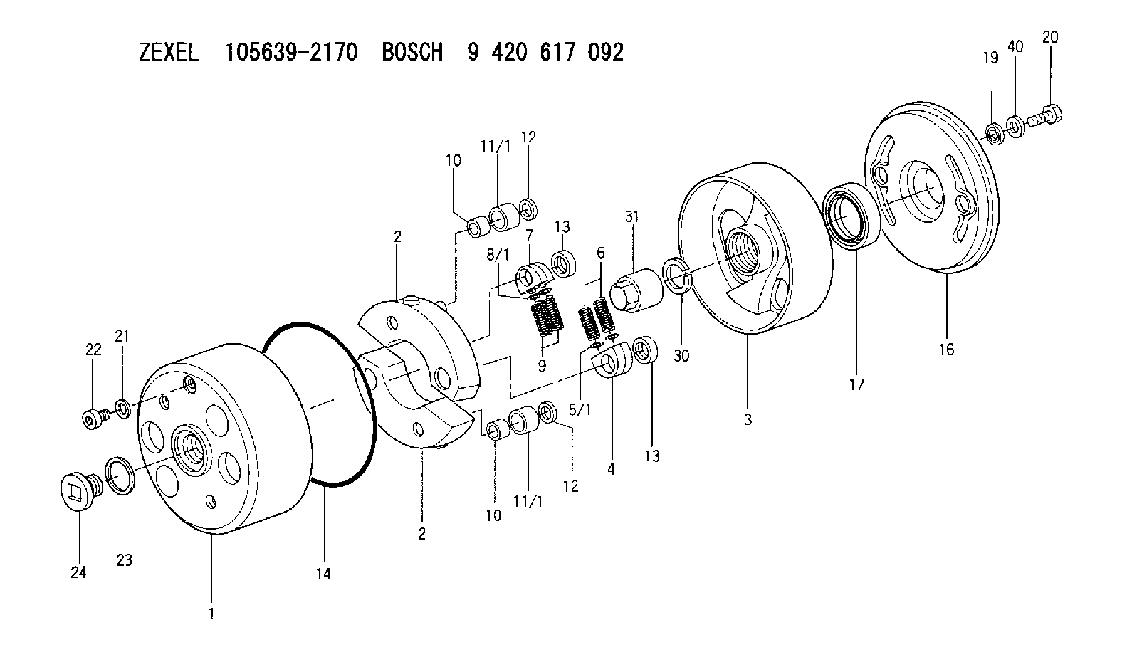
| 1. | [1] | 156350-0420 | TIMING-DEVICE HOUSING |
| 2. | [2] | 156355-2520 | FLYWEIGHT |
| 2. | [2] | 156355-2520 | FLYWEIGHT |
| 3. | [1] | 156352-2020 | FLANGE BUSHING |
| 4. | [2] | 156360-0100 | SLOTTED WASHER |
| 5/1. | [0] | 156373-0000 | SHIM D19&10.2T0.2 |
| 5/1. | [0] | 156373-0100 | SHIM D19&10.2T0.3 |
| 5/1. | [0] | 156373-0200 | SHIM D19&10.2T0.5 |
| 6. | [2] | 156361-0700 | COMPRESSION SPRING |
| 7. | [2] | 156360-0100 | SLOTTED WASHER |
| 8/1. | [0] | 156373-0000 | SHIM D19&10.2T0.2 |
| 8/1. | [0] | 156373-0100 | SHIM D19&10.2T0.3 |
| 8/1. | [0] | 156373-0200 | SHIM D19&10.2T0.5 |
| 9. | [2] | 156361-0700 | COMPRESSION SPRING |
| 10. | [2] | 156362-0000 | BUSHING |
| 10. | [2] | 156362-0000 | BUSHING |
| 11/1. | [1] | 156363-0000 | ROLLER D27.90 |
| 11/1. | [1] | 156363-0100 | ROLLER D28.00 |
| 11/1. | [1] | 156363-0100 | ROLLER D28.00 |
| 11/1. | [1] | 156363-0200 | ROLLER D28.10 |
| 11/1. | [1] | 156363-0300 | ROLLER D28.20 |
| 12. | [2] | 156368-0000 | PLAIN WASHER |
| 12. | [2] | 156368-0000 | PLAIN WASHER |
| 13. | [2] | 156367-0000 | RETAINER |
| 13. | [2] | 156367-0000 | RETAINER |
| 14. | [1] | 156365-0100 | O-RING |
| 16. | [1] | 156358-0100 | COVER |
| 17. | [1] | 156309-0300 | PACKING RING |
| 19. | [2] | 156372-0020 | GASKET |
| 20. | [2] | 156371-0000 | BLEEDER SCREW |
| 21. | [1] | 029331-0190 | GASKET D14&10.2T1 |
| 22. | [1] | 156316-0000 | CAPSULE |
| 23. | [1] | 156319-0200 | GASKET |
| 24. | [1] | 156314-0600 | CAP |
| 30. | [1] | 156322-0100 | LOCKING WASHER |
| 31. | [1] | 134325-0100 | UNION NUT |
| 40. | [6] | 029311-0440 | SHIM D18&10.3T0.40 |
Cross reference number
Zexel num
Bosch num
Firm num
Name
105639-2170
AUTOM. ADVANCE MECHANISM
K 14KD AUTOMATIC TIMER TIMER SP(Z) TIMER
K 14KD AUTOMATIC TIMER TIMER SP(Z) TIMER
Information:
start by:a) remove oil pump1. Turn the crankshaft until two pistons are at bottom center. Remove the connecting rod caps from the two connecting rods. Remove the lower half of the bearings from the caps.2. Push the connecting rods away from the crankshaft and remove the upper half of the bearings.3. Clean the bearing contact surfaces in the caps and rods. Install the upper halves of the bearings in the connecting rods. Put clean SAE 30 engine oil on the bearings and crankshaft journals. Put the connecting rods in position on the crankshaft.4. Install the lower halves of the new bearings in the caps. Put clean SAE 30 engine oil on the bearings and on the threads of all bolts. 5. Put Plastigage (A) on the bearing to check the bearing clearance. Put the caps in position on the connecting rods and install the nuts on the bolts. Tighten the nuts to a torque of 30 3 lb.ft. (40 4 N m). Put a mark across the nuts and bolts, and turn the nuts 90° more from the marks as shown. 6. Remove the rod cap and measure the thickness of the Plastigage to find the bearing clearance. Clearance with new bearings must be .0030 to .0066 in. (0.076 to 0.168 mm). Maximum permissible clearance with used bearings is .010 in. (0.25 mm).7. Put clean oil on the lower halves of the bearings and on the threads of the bolts. Put the caps in position on the connecting rods and install the nuts on the bolts. Tighten both nuts to a torque of 30 3 lb.ft. (40 4 N m). Put a mark across the nuts and bolts, and turn the nuts 90° more from the mark as shown.
Make sure the number on the side of the connecting rod is the same number and on the same side as the number on the cap.
8. Do the above steps again for the remainder of the connecting rod bearings.end by:a) install oil pump
Make sure the number on the side of the connecting rod is the same number and on the same side as the number on the cap.
8. Do the above steps again for the remainder of the connecting rod bearings.end by:a) install oil pump