Information autom. advance mechanism
BOSCH
9 420 615 772
9420615772
ZEXEL
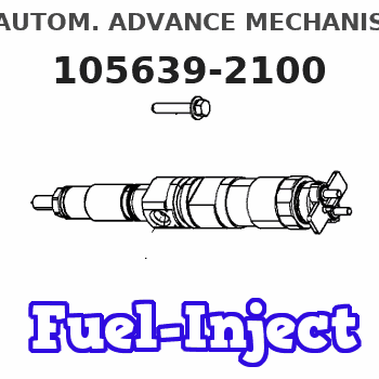
105639-2100
1056392100
Rating:
Scheme ###:
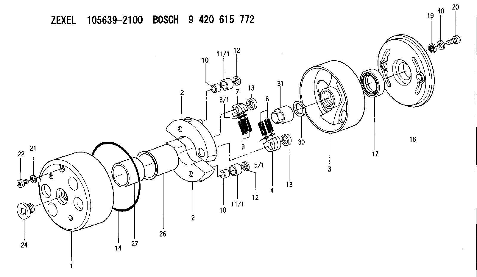
| 1. | [1] | 156350-0220 | TIMING-DEVICE HOUSING |
| 2. | [2] | 156355-2420 | FLYWEIGHT |
| 2. | [2] | 156355-2420 | FLYWEIGHT |
| 3. | [1] | 156352-1120 | FLANGE BUSHING |
| 4. | [2] | 156360-0100 | SLOTTED WASHER |
| 5/1. | [0] | 156373-0000 | SHIM D19&10.2T0.2 |
| 5/1. | [0] | 156373-0100 | SHIM D19&10.2T0.3 |
| 5/1. | [0] | 156373-0200 | SHIM D19&10.2T0.5 |
| 6. | [2] | 156361-2200 | COMPRESSION SPRING |
| 7. | [2] | 156360-0100 | SLOTTED WASHER |
| 8/1. | [0] | 156373-0000 | SHIM D19&10.2T0.2 |
| 8/1. | [0] | 156373-0100 | SHIM D19&10.2T0.3 |
| 8/1. | [0] | 156373-0200 | SHIM D19&10.2T0.5 |
| 9. | [2] | 156361-2200 | COMPRESSION SPRING |
| 10. | [2] | 156362-0000 | BUSHING |
| 10. | [2] | 156362-0000 | BUSHING |
| 11/1. | [1] | 156363-0000 | ROLLER D27.90 |
| 11/1. | [1] | 156363-0100 | ROLLER D28.00 |
| 11/1. | [1] | 156363-0200 | ROLLER D28.10 |
| 11/1. | [1] | 156363-0200 | ROLLER D28.10 |
| 11/1. | [1] | 156363-0300 | ROLLER D28.20 |
| 12. | [2] | 156368-0000 | PLAIN WASHER |
| 12. | [2] | 156368-0000 | PLAIN WASHER |
| 13. | [2] | 156367-0000 | RETAINER |
| 13. | [2] | 156367-0000 | RETAINER |
| 14. | [1] | 156365-0000 | O-RING |
| 16. | [1] | 156358-0100 | COVER |
| 17. | [1] | 156309-0000 | PACKING RING |
| 19. | [2] | 156372-0020 | GASKET |
| 20. | [2] | 156371-0000 | BLEEDER SCREW |
| 21. | [1] | 029331-0190 | GASKET D14&10.2T1 |
| 22. | [1] | 156316-0000 | CAPSULE |
| 24. | [1] | 156314-0501 | CAP |
| 26. | [1] | 156369-0000 | BUSHING |
| 27. | [1] | 156370-0000 | SPACER RING |
| 30. | [1] | 029321-8020 | LOCKING WASHER |
| 31. | [1] | 134325-0100 | UNION NUT |
| 40. | [6] | 029311-0440 | SHIM D18&10.3T0.40 |
Include in #1:
106671-4030
as AUTOM. ADVANCE MECHANIS
Cross reference number
Zexel num
Bosch num
Firm num
Name
105639-2100
AUTOM. ADVANCE MECHANISM
K 14KD AUTOMATIC TIMER TIMER SP(Z) TIMER
K 14KD AUTOMATIC TIMER TIMER SP(Z) TIMER
Information:
start by: a) remove fuel injection pump housing and governor1. Put the fuel injection pump housing on tool (A). 2. Remove bolts (1). 3. Remove bolt (2). Remove adapter housing (3) from the pump housing. 4. Remove bolts (4) and (5). Loosen bolt (6). 5. Remove governor housing (7) from the pump housing. 6. Remove spring (12), wave washer (11) and guide (10). Remove seat (8) and over fueling spring (9). 7. Pull shaft (13) up and remove it. Remove lever (14) from the housing. 8. Remove riser (follower) (17) from the shaft. Remove ring (15) and lever (16). 9. Remove cover (18) with tool (B). Tool (B) can cause damage to the cover. Always inspect the cover and install a new cover if needed.10. Install the timing pin to prevent the camshaft from turning. 11. Remove three bolts (19) that hold the flyweight assembly to the camshaft. Remove the flyweight assembly from the pump housing.12. Remove the timing pin.Connection Of Governor To Fuel Injection Pump Housing
1. Put the fuel injection pump housing on tool (A).2. Install the timing pin to prevent the camshaft from turning. 3. Put flyweight assembly (1) in position on the camshaft.
Be sure pin (2) that holds the shaft is in the correct position on back of the flyweight assembly.
4. Install new bolts for the flyweight assembly. The bolts for the flyweight assembly have a locking material on the threads and must not be used more than one time. 5. Install the cover over the flyweight assembly with tool (B). 6. Grind a taper on the bottom edge of a 1/8" screwdriver (3). Install the screwdriver through the bolt hole in the governor housing. The screwdriver must fit evenly against the flyweight assembly cover. Make a mark (stake) in four places around the cover in line with the groove in the camshaft.
Never install a used flyweight cover that is bent.
7. Install lever (4) on the dowel. Install ring (5). 8. Put riser (follower) (6) in position between the flyweights. Lift the flyweight up with a piece of wire and push the riser (follower) forward. 9. Put lever (10) in position. Lever (10) will be in the correct position when the lever end is in the groove of riser (follower) (6) and the ball end is engaged in sleeve shaft lever (9).
If lever (10) is not installed correctly, the governor can not operate and can cause the engine to over speed.
10. Install O-ring (7). Install shaft (8) to hold lever (10) in place. 11. Install over fueling spring (12) and seat (11) on the shaft. 12. Install guide (13), (wave) washer (14) and spring (15) in the governor housing.13. Put the governor housing on the fuel injection pump housing and install the bolts.end by: a) install adapter housing and leversb) install fuel injection pump housing and governorc) make adjustment of fuel system setting (See Fuel System Setting in Testing and Adjusting)