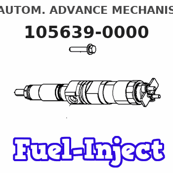
Information autom. advance mechanism
BOSCH
9 420 616 503
9420616503
ZEXEL
105639-0000
1056390000
NISSAN-DIESEL
1685197003
1685197003
Rating:
Scheme ###:
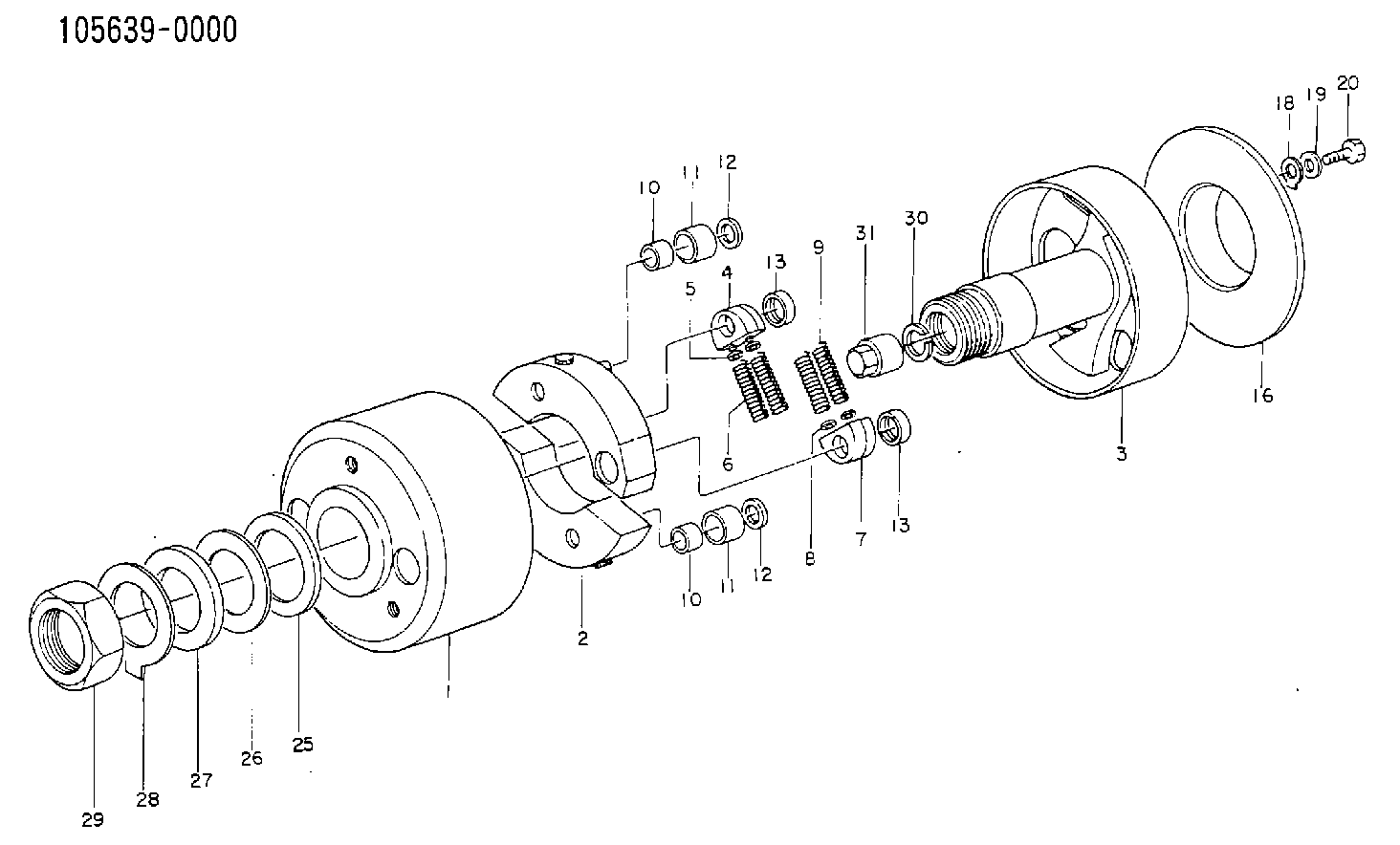
| 1. | [1] | 156300-0722 | TIMING-DEVICE HOUSING |
| 2. | [2] | 156305-0820 | FLYWEIGHT |
| 3. | [1] | 156302-2220 | FLANGE BUSHING |
| 4. | [2] | 156310-0000 | SLOTTED WASHER |
| 5/1. | [0] | 029310-8520 | SHIM D14&8.4T0.2 |
| 5/1. | [0] | 029310-8530 | SHIM D14&8.4T0.4 |
| 5/1. | [0] | 029310-8540 | SHIM D14&8.4T0.5 |
| 5/1. | [0] | 029310-8550 | SHIM D14&8.4T0.6 |
| 5/1. | [0] | 029310-8560 | SHIM D14&8.4T0.7 |
| 5/1. | [0] | 029310-8680 | SHIM D14&8.4T1.0 |
| 5/1. | [0] | 139408-0000 | SHIM D14&8.4T0.30 |
| 5/1. | [0] | 139408-0100 | SHIM D14&8.4T0.80 |
| 5/1. | [0] | 139408-0200 | SHIM D14&8.4T0.90 |
| 5/1. | [0] | 139408-0300 | SHIM D14&8.4T0.10 |
| 5/1. | [0] | 139408-0500 | SHIM D14&8.4T1.5 |
| 5/1. | [0] | 139408-0600 | SHIM D14&8.4T2.0 |
| 6. | [2] | 156311-0700 | COMPRESSION SPRING |
| 7. | [2] | 156310-0100 | SLOTTED WASHER |
| 8/1. | [0] | 029310-8520 | SHIM D14&8.4T0.2 |
| 8/1. | [0] | 029310-8530 | SHIM D14&8.4T0.4 |
| 8/1. | [0] | 029310-8540 | SHIM D14&8.4T0.5 |
| 8/1. | [0] | 029310-8550 | SHIM D14&8.4T0.6 |
| 8/1. | [0] | 029310-8560 | SHIM D14&8.4T0.7 |
| 8/1. | [0] | 029310-8680 | SHIM D14&8.4T1.0 |
| 8/1. | [0] | 139408-0000 | SHIM D14&8.4T0.30 |
| 8/1. | [0] | 139408-0100 | SHIM D14&8.4T0.80 |
| 8/1. | [0] | 139408-0200 | SHIM D14&8.4T0.90 |
| 8/1. | [0] | 139408-0300 | SHIM D14&8.4T0.10 |
| 8/1. | [0] | 139408-0500 | SHIM D14&8.4T1.5 |
| 8/1. | [0] | 139408-0600 | SHIM D14&8.4T2.0 |
| 9. | [2] | 156311-4300 | COMPRESSION SPRING |
| 10. | [2] | 156312-0000 | BUSHING |
| 10. | [2] | 156312-0000 | BUSHING |
| 11/1. | [1] | 156313-0000 | ROLLER D23.9 |
| 11/1. | [1] | 156313-0000 | ROLLER D23.9 |
| 11/1. | [1] | 156313-0100 | ROLLER D24.0 |
| 11/1. | [1] | 156313-0200 | ROLLER D24.1 |
| 11/1. | [1] | 156313-0300 | ROLLER D24.2 |
| 12. | [2] | 029301-2250 | PLAIN WASHER D23&12T3.5 |
| 12. | [2] | 029301-2250 | PLAIN WASHER D23&12T3.5 |
| 13. | [2] | 156317-0000 | RETAINER |
| 13. | [2] | 156317-0000 | RETAINER |
| 16. | [1] | 156308-0400 | COVER |
| 18. | [2] | 156210-1200 | LOCKING LEVER |
| 19. | [2] | 156615-2000 | PLAIN WASHER |
| 20. | [2] | 156603-9500 | BLEEDER SCREW |
| 25. | [1] | 156269-0100 | PLAIN WASHER |
| 26/1. | [0] | 029315-2000 | SHIM D70&52.2T0.1 |
| 26/1. | [0] | 029315-2010 | SHIM D70&52.2T0.12 |
| 26/1. | [0] | 029315-2020 | SHIM D70&52.2T0.15 |
| 26/1. | [0] | 029315-2030 | SHIM D70&52.2T0.2 |
| 26/1. | [0] | 029315-2040 | SHIM D70&52.2T0.3 |
| 27. | [1] | 029304-8000 | PLAIN WASHER |
| 28. | [1] | 156270-0100 | LOCKING LEVER |
| 29. | [1] | 029204-8000 | UNION NUT |
| 30. | [1] | 029321-8020 | LOCKING WASHER |
| 31. | [1] | 134325-0100 | UNION NUT |
Cross reference number
Zexel num
Bosch num
Firm num
Name
1685197003 NISSAN-DIESEL
AUTOM. ADVANCE MECHANISM
* K 14KD AUTOMATIC TIMER TIMER SP(Z) TIMER
* K 14KD AUTOMATIC TIMER TIMER SP(Z) TIMER
Information:
start by:a) remove pistons1. Remove the bearings from the connecting rod and connecting rod cap. 2. Remove retainer ring (1) with tool (C).3. Remove pin (2) and the connecting rod (4) from the piston (3). 4. Remove the piston rings from the piston with tool (A). Clean the piston ring grooves on the pistons with an acceptable ring groove cleaning tool. See USE OF PISTON PIN BEARING REMOVAL AND INSTALLATION TOOLS, SPECIAL INSTRUCTION, Form No. SMHS7295.5. Heat the connecting rod in an oven to a temperature of 350°-500°F (177°-260°C). Never use a direct flame to heat a connecting rod. 6. Put connecting rod (4) in position on the base plate of tooling (B). Put a new rod pin bearing (5) on the adapter part of tooling (B). Make sure that the joint in the rod pin bearing is 90° from a center line through the crankshaft and pin bearing bores. 7. Install the pusher adapter (7) and pusher (8) part of tooling (B) on the adapter. The old bearing is pushed out by tooling (B) as the new bearing is installed.8. Use tooling (B) to push the new bearing into the connecting rod until the push adapter of tooling (B) makes full contact with the connecting rod surface.9. Use a pin boring machine to make the rod pin bearing the correct size. The bore in the new rod pin bearing must be 2.0012 .0003 in. (50.830 0.008 mm).10. Check the clearance between the ends of the piston rings. See PISTONS AND RINGS in SPECIFICATIONS.11. Install the oil ring spring in the oil ring groove of the piston. The oil ring is to be installed over the spring with the oil ring end gap 180° from the oil ring spring joint. 12. Install the oil ring on the piston with tool (A).13. Install the second (intermediate) piston ring with the side that has the identification "UP-2" toward the top of the piston with tool (A).14. Install the first (top) piston ring with the side that has the identification "UP-1" toward the top of the piston with tool (A). After the installation of all three piston rings, put the piston ring in position so the end gaps are 120° apart. 15. Put piston (3) in position on connecting rod (4). Put clean engine oil on pin (2) and install the pin. Install retainer rings (1) with tool (C). Make sure the retainer rings are in the grooves of the piston.16. Install the bearings in the connecting rod and connecting rod cap.end by:a) install pistons