Information autom. advance mechanism
BOSCH
9 420 615 939
9420615939
ZEXEL
105636-1740
1056361740
NISSAN-DIESEL
1685197509
1685197509

Rating:
Scheme ###:
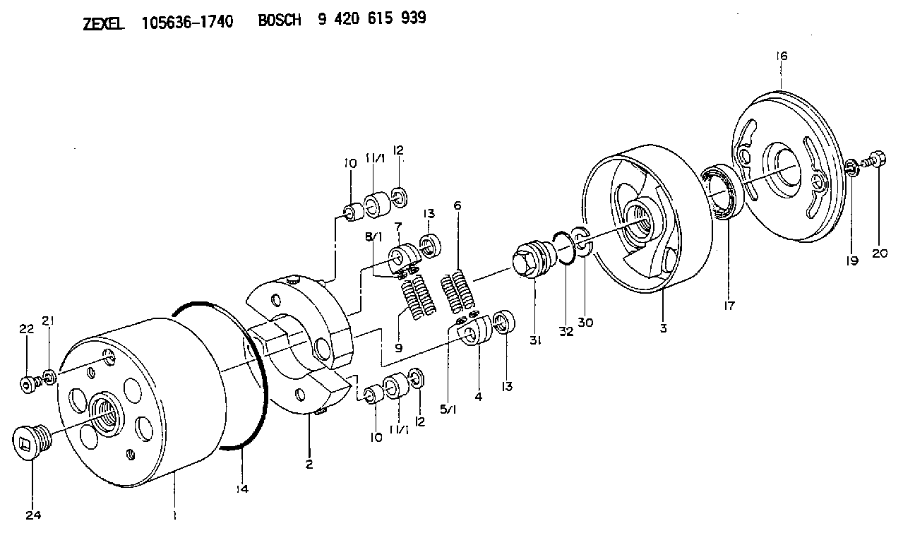
| 1. | [1] | 156300-2022 | TIMING-DEVICE HOUSING |
| 2. | [2] | 156305-5320 | FLYWEIGHT |
| 3. | [1] | 156302-5020 | FLANGE BUSHING |
| 4. | [2] | 156310-0000 | SLOTTED WASHER |
| 5/1. | [0] | 029310-8520 | SHIM D14&8.4T0.2 |
| 5/1. | [0] | 029310-8530 | SHIM D14&8.4T0.4 |
| 5/1. | [0] | 029310-8540 | SHIM D14&8.4T0.5 |
| 5/1. | [0] | 029310-8550 | SHIM D14&8.4T0.6 |
| 5/1. | [0] | 029310-8560 | SHIM D14&8.4T0.7 |
| 5/1. | [0] | 029310-8680 | SHIM D14&8.4T1.0 |
| 5/1. | [0] | 139408-0000 | SHIM D14&8.4T0.30 |
| 5/1. | [0] | 139408-0100 | SHIM D14&8.4T0.80 |
| 5/1. | [0] | 139408-0200 | SHIM D14&8.4T0.90 |
| 5/1. | [0] | 139408-0300 | SHIM D14&8.4T0.10 |
| 5/1. | [0] | 139408-0500 | SHIM D14&8.4T1.5 |
| 5/1. | [0] | 139408-0600 | SHIM D14&8.4T2.0 |
| 6. | [2] | 156311-6500 | COMPRESSION SPRING |
| 7. | [2] | 156310-0000 | SLOTTED WASHER |
| 8/1. | [0] | 029310-8520 | SHIM D14&8.4T0.2 |
| 8/1. | [0] | 029310-8530 | SHIM D14&8.4T0.4 |
| 8/1. | [0] | 029310-8540 | SHIM D14&8.4T0.5 |
| 8/1. | [0] | 029310-8550 | SHIM D14&8.4T0.6 |
| 8/1. | [0] | 029310-8560 | SHIM D14&8.4T0.7 |
| 8/1. | [0] | 029310-8680 | SHIM D14&8.4T1.0 |
| 8/1. | [0] | 139408-0000 | SHIM D14&8.4T0.30 |
| 8/1. | [0] | 139408-0100 | SHIM D14&8.4T0.80 |
| 8/1. | [0] | 139408-0200 | SHIM D14&8.4T0.90 |
| 8/1. | [0] | 139408-0300 | SHIM D14&8.4T0.10 |
| 8/1. | [0] | 139408-0500 | SHIM D14&8.4T1.5 |
| 8/1. | [0] | 139408-0600 | SHIM D14&8.4T2.0 |
| 9. | [2] | 156311-6500 | COMPRESSION SPRING |
| 10. | [2] | 156312-0000 | BUSHING |
| 10. | [2] | 156312-0000 | BUSHING |
| 11/1. | [1] | 156313-0000 | ROLLER D23.9 |
| 11/1. | [1] | 156313-0100 | ROLLER D24.0 |
| 11/1. | [1] | 156313-0100 | ROLLER D24.0 |
| 11/1. | [1] | 156313-0200 | ROLLER D24.1 |
| 11/1. | [1] | 156313-0300 | ROLLER D24.2 |
| 12. | [2] | 029301-2250 | PLAIN WASHER D23&12T3.5 |
| 12. | [2] | 029301-2250 | PLAIN WASHER D23&12T3.5 |
| 13. | [2] | 156317-0100 | RETAINER |
| 13. | [2] | 156317-0100 | RETAINER |
| 14. | [1] | 156315-0200 | O-RING |
| 16. | [1] | 156308-0600 | COVER |
| 17. | [1] | 156309-0000 | PACKING RING |
| 19. | [2] | 156319-0100 | GASKET |
| 20. | [2] | 156633-4800 | BLEEDER SCREW |
| 21. | [1] | 029331-0190 | GASKET D14&10.2T1 |
| 22. | [1] | 156316-0000 | CAPSULE |
| 24. | [1] | 156314-0501 | CAP |
| 30. | [1] | 029321-8020 | LOCKING WASHER |
| 31. | [1] | 134325-0300 | UNION NUT |
| 32. | [1] | 029632-8010 | O-RING |
Cross reference number
Zexel num
Bosch num
Firm num
Name
Information:
Introduction
The problem that is identified below has a known solution. Use the solution that is identified below.Problem
The procedure for the Disassembly and Assembly needs to be updated to include the information below.Solution
Do not operate or work on this product unless you have read and understood the instruction and warnings in the relevant Operation and Maintenance Manuals and relevant service literature. Failure to follow the instructions or heed the warnings could result in injury or death. Proper care is your responsibility.
Inspect the quill tubes and fuel injectors for cuts or marks at the mating surfaces.
Replace any quill tubes since the quill tubes are a one time use component. Replace the copper washer when replacing the fuel injector.
Follow the steps below for installing the quill tunes and fuel injectors.
Seat the injector by installing and torquing the injector hold down clamp bolt to 30 3 N m (22 2 lb ft).
Install the quill tube and tighten the quill nut between 15 N m (11 lb ft) to 20 N m (15 lb ft).
Apply a final torque of 30 3 N m (22 2 lb ft) to the injector hold down clamp bolt.
Apply a final torque between 50 N m (37 lb ft) to 55 N m (41 lb ft).