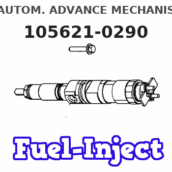
Information autom. advance mechanism
BOSCH
9 420 615 054
9420615054
ZEXEL
105621-0290
1056210290
ISUZU
9813400910
9813400910
Rating:
Scheme ###:
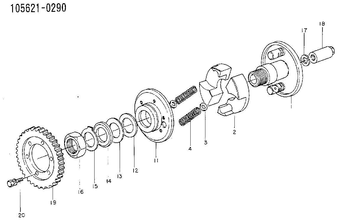
| 1. | [1] | 156206-1320 | FLYWEIGHT ASSEMBLY |
| 2. | [2] | 156205-4200 | FLYWEIGHT |
| 3/1. | [0] | 029310-7010 | SHIM D14.5&7T0.1 |
| 3/1. | [0] | 029310-7020 | SHIM D14.5&7T0.3 |
| 3/1. | [0] | 029310-7030 | SHIM D14.5&7T0.5 |
| 3/1. | [0] | 029310-7040 | SHIM D14.5&7T0.2 |
| 3/1. | [0] | 029310-7050 | SHIM D14.5&7T0.6 |
| 3/1. | [0] | 029310-7060 | SHIM D14.5&7T1.0 |
| 3/1. | [0] | 139440-0600 | SHIM D14.5&7.0T0.40 |
| 3/1. | [0] | 139440-0700 | SHIM D14.5&7.0T0.70 |
| 3/1. | [0] | 139440-0800 | SHIM D14.5&7.0T0.80 |
| 3/1. | [0] | 139440-0900 | SHIM D14.5&7.0T0.90 |
| 4. | [2] | 156203-0700 | COMPRESSION SPRING |
| 11. | [1] | 156201-1720 | FLANGE BUSHING |
| 12. | [1] | 156209-0400 | PLAIN WASHER |
| 13/1. | [0] | 156215-0000 | SHIM D38&31.5T0.12 |
| 13/1. | [0] | 156215-0100 | SHIM D38&31.5T0.14 |
| 13/1. | [0] | 156215-0200 | SHIM D38&31.5T0.16 |
| 13/1. | [0] | 156215-0300 | SHIM D38&31.5T0.18 |
| 13/1. | [0] | 156215-0400 | SHIM D38&31.5T0.5 |
| 13/1. | [0] | 156215-0500 | SHIM D38&31.5T0.2 |
| 13/1. | [0] | 156215-0600 | SHIM D38&31.5T0.3 |
| 13/1. | [0] | 156215-0700 | SHIM D38&31.5T0.1 |
| 13/1. | [0] | 156215-0800 | SHIM D38&31.5T0.25 |
| 13/1. | [0] | 156215-0900 | SHIM D38&31.5T0.4 |
| 14. | [1] | 156214-0000 | PLAIN WASHER |
| 15. | [1] | 156210-0100 | LOCKING LEVER |
| 16. | [1] | 029202-8010 | UNION NUT |
| 17. | [1] | 023641-2410 | LOCKING WASHER |
| 18. | [1] | 131325-0500 | UNION NUT |
| 19. | [1] | 156211-5400 | TOOTHED GEAR |
| 20. | [6] | 139006-4300 | BLEEDER SCREW |
Include in #1:
101431-0010
as AUTOM. ADVANCE MECHANIS
Cross reference number
Zexel num
Bosch num
Firm num
Name
105621-0290
9813400910 ISUZU
AUTOM. ADVANCE MECHANISM
K 14KA AUTOMATIC TIMER TIMER SCD TIMER
K 14KA AUTOMATIC TIMER TIMER SCD TIMER
Information:
1 Remove the plug from the dash and install 3T306 Starting Aid Switch. Connect two purple wires, from the wiring harness, to the switch. 2 Put 3T157 Support Assembly (1) in position. Install two 6H1717 Bolts (2) as shown. On D6D Tractors with 4N6016 Refrigerant Compressor Group, remove the existing spacer so support (1) will fit at location (A); use the existing bolt. Remove the bolt and washer from the cylinder head and put 3T1417 Brace (3) in position. Install 2A4256 Spacer (4), S1591 Bolt (5) and 5M2894 Washer. Do not use spacer (4) on D6D Tractors. Install S1594 Bolt (6) and 5M2894 Washer. 3 Put 6N7674 Valve Assembly (7) in position on support assembly (1) and install two S1618 Bolts (8), 5P4116 Washers and 1D4716 Nuts. Put 7N2059 Clamp Assembly (9) in position on the support assembly and install two S1618 Bolts (8), 5P4116 Washers and 1D4716 Nuts. 4 Remove the plug from the manifold and install 6N9995 Atomizer Assembly (9). The orifices of the atomizer must be toward each end of the manifold. Install 5P7907 Connector (10) in valve assembly (7). Install one end of 9P3121 Tube (11) in atomizer assembly (9) and connect the other end of tube (11) to connector (10) with 5P6314 Sleeve (12) and 5P6313 Nut (13). Remove the plug from the bypass elbow and install 6N5899 Switch (14). Connect 9G3005 Wire Assembly (15) to switch (14) and to one wire from valve assembly (7). 5 Install 3D5102 Grommet and 2B2404 Clip (16) to hold tube (11). Connect 9G3006 Wire Assembly (17) to valve assembly (7) and to the purple wire, from the starting aid switch, at the rear of the engine. Use former clips (18) to hold wire assembly (17) in position.6 Remove cap (19) from valve assembly (7) and install 7N296 Cylinder Assembly.