Information autom. advance mechanism
BOSCH
9 420 616 206
9420616206
ZEXEL
105614-3400
1056143400
Rating:
Scheme ###:
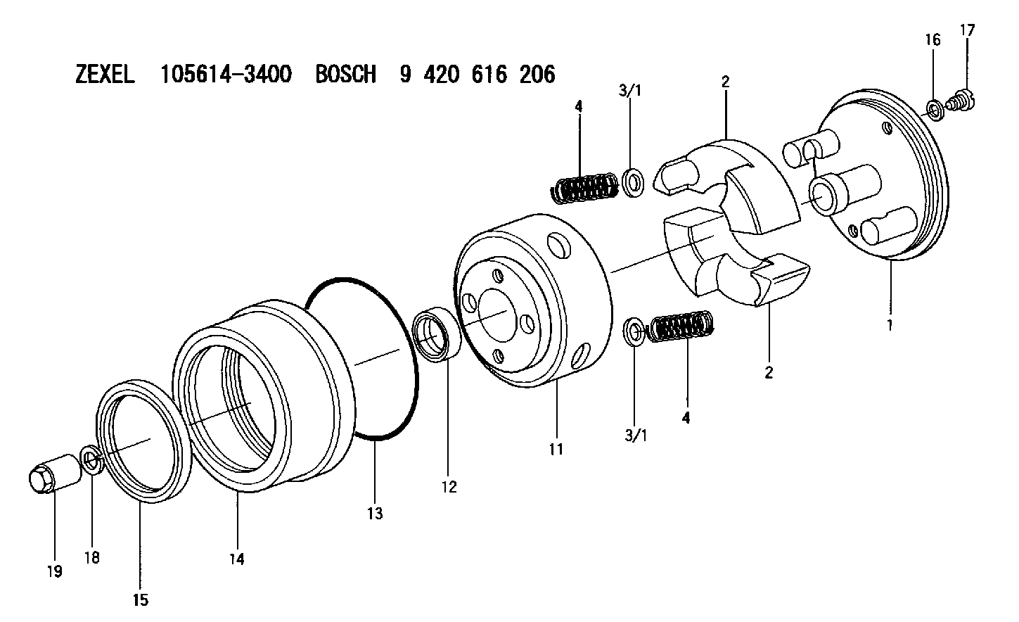
| 1. | [1] | 156132-9020 | FLYWEIGHT ASSEMBLY |
| 2. | [2] | 156108-5900 | FLYWEIGHT |
| 2. | [2] | 156108-5900 | FLYWEIGHT |
| 3/1. | [0] | 029310-9010 | SHIM D19.6&9T0.5 |
| 3/1. | [0] | 029310-9010 | SHIM D19.6&9T0.5 |
| 3/1. | [0] | 029310-9020 | SHIM D19.6&9T1 |
| 3/1. | [0] | 029310-9030 | SHIM D19.6&9T0.1 |
| 3/1. | [0] | 029310-9040 | SHIM D19.6&9T0.2 |
| 3/1. | [0] | 029310-9050 | PLAIN WASHER D19.6&9T1.5 |
| 3/1. | [0] | 139409-0000 | SHIM D19.6&9.0T0.15 |
| 4. | [2] | 156125-2200 | COMPRESSION SPRING |
| 4. | [2] | 156125-2200 | COMPRESSION SPRING |
| 11. | [1] | 156130-7420 | FLANGE BUSHING |
| 12. | [1] | 029622-8010 | PACKING RING |
| 13. | [1] | 156117-0100 | O-RING |
| 14. | [1] | 156114-1400 | CASE |
| 15. | [1] | 156116-2220 | PACKING RING |
| 16. | [2] | 026508-1240 | GASKET D11.9&8.2T1 |
| 17. | [2] | 156115-0100 | CAPSULE |
| 18. | [1] | 029321-4010 | LOCKING WASHER |
| 19. | [1] | 131325-0400 | UNION NUT |
Include in #1:
101603-9033
as AUTOM. ADVANCE MECHANIS
Cross reference number
Zexel num
Bosch num
Firm num
Name
Information:
Transmission Oil Cooler
The machine is equipped with a power shift transmission. A transmission oil cooler is installed in the outlet section of the radiator. The radiator coolant flows around the tubes of the cooler and cools the transmission oil as it flows through the cooler. The transmission oil then returns to the transmission inlet.Lubrication System
Oil Pump
(1) Strainer. (2) Oil pump relief valve. (3) Oil pump. (4) Idler gear. (5) Crankshaft gear.The lubrication system is the pressure type and the flow of oil goes from the oil pan through strainer (1) into oil pump (3). Oil pump (3) is driven by crankshaft gear (5) through the idler gear (4). The oil pump is connected to the front main bearing cap. Relief valve (2) which is spring loaded controls the maximum oil pressure. An oil pressure sending unit is connected to the main oil gallery.Oil under pressure goes from the oil pump through the relief valve, oil filter and into the main oil gallery that is a drilled passage the length of the crankcase. From the gallery the oil flows through drilled passages to the main bearing bores and then through the crankshaft passages to the big end (rod) bearings. The small end (rod) bearings, cylinder liners and pistons get splash lubrication from the big end (rod) bearings.The camshaft front bearing and journals are lubricated from numbers 1, 3 and 5 main bearings. The camshaft center journal supplies a controlled amount of oil to the rocker shaft assembly. Oil from the rocker shaft drains through a bleed hole in each rocker lever to lubricate the valves, guides, tappets (valve lifters) and cam lobes.
Timing Gears
(6) Idler gear. (7) Idler gear retainer plate.Oil also goes from the gallery through the rear of idler gear (6) hub, then through passages to lubricate the idler gear bearing and gear retainer plate (7). On engines equipped with hydraulic governed fuel injection pumps, the fuel pump adapter plate is also lubricated from the main oil gallery. The timing gears are splash lubricated from the idler gear hub.
Oil Lubrication SchematicAir Inlet And Exhaust System
Air Inlet Components
(1) Intake manifold. (2) Exhaust manifold.
Air Inlet Components
(3) Air cleaner.The air inlet and exhaust system components are: air cleaner (3), intake manifold (1), an air inlet hose, an air indicator, the cylinder head valves and valve mechanism components, exhaust manifold (2), pipe and muffler.Air is pulled in the air inlet system by the intake stroke of the piston. The air flows in air cleaner (3), through air inlet hose that directs the volume of air to intake manifold (1). The air flows through intake manifold (1) which directs even distribution of the air to each cylinder where the air is mixed with fuel from the injectors. The sequence and action of the engines' four cylinders and four strokes, (compression, power, exhaust and intake) give constant air flow to the intake system for engine operation.An air indicator located on the air inlet hose shows a red indication when too much air restriction (dirt)