Information autom. advance mechanism
BOSCH
9 420 617 210
9420617210
ZEXEL
105612-3290
1056123290
Rating:
Scheme ###:
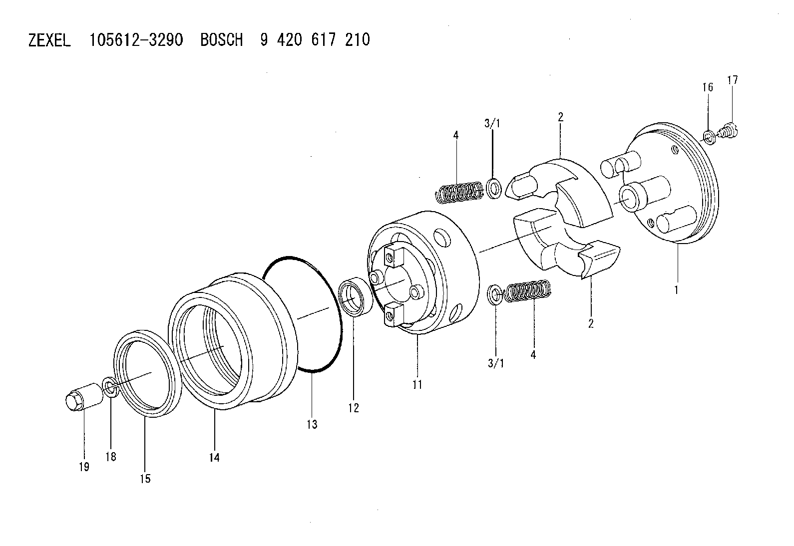
| 1. | [1] | 156133-1720 | FLYWEIGHT ASSEMBLY |
| 2. | [2] | 156108-5900 | FLYWEIGHT |
| 2. | [2] | 156108-5900 | FLYWEIGHT |
| 3/1. | [0] | 029310-9010 | SHIM D19.6&9T0.5 |
| 3/1. | [0] | 029310-9020 | SHIM D19.6&9T1 |
| 3/1. | [0] | 029310-9030 | SHIM D19.6&9T0.1 |
| 3/1. | [0] | 029310-9040 | SHIM D19.6&9T0.2 |
| 3/1. | [0] | 029310-9050 | PLAIN WASHER D19.6&9T1.5 |
| 3/1. | [0] | 029310-9050 | PLAIN WASHER D19.6&9T1.5 |
| 3/1. | [0] | 139409-0000 | SHIM D19.6&9.0T0.15 |
| 4. | [2] | 156124-3900 | COMPRESSION SPRING |
| 4. | [2] | 156124-3900 | COMPRESSION SPRING |
| 11. | [1] | 156130-9020 | FLANGE BUSHING |
| 12. | [1] | 029622-8010 | PACKING RING |
| 13. | [1] | 156117-0100 | O-RING |
| 14. | [1] | 156114-1300 | CASE |
| 15. | [1] | 156116-1020 | PACKING RING |
| 16. | [2] | 026508-1240 | GASKET D11.9&8.2T1 |
| 17. | [2] | 156115-0100 | CAPSULE |
| 18. | [1] | 014111-2420 | LOCKING WASHER |
| 19. | [1] | 131325-0200 | UNION NUT |
Include in #1:
101681-9520
as AUTOM. ADVANCE MECHANIS
Cross reference number
Zexel num
Bosch num
Firm num
Name
105612-3290
9 420 617 210
AUTOM. ADVANCE MECHANISM
* K
* K
Information:
Engine Runs Smoothly1. Poor Quality Fuel If poor or low quality fuel is suspected, use a source of known good quality fuel, and prime and start the engine. If the problem is resolved, drain the complete fuel system, replace the fuel filter, and add fuel recommended by Caterpillar.2. Fuel Injection Timing Out Of Calibration Check the fuel injection timing calibration and make necessary calibrations. See Engine Test Procedure Number P-301 in Electronic Troubleshooting, 3176 Vehicular Diesel Engine, Form No. SENR5137.3. Air Inlet Piping Damage Or Restriction Visually inspect the air inlet system for damage or restriction. If leaks are found, repair or replace parts as required.If the air cleaner has an Air Cleaner Service Indicator, check the indicator for the position of the red piston. If the indicator shows red at any time, install a clean or new air cleaner element.Air inlet restriction can be checked with a water manometer or a vacuum gauge [measuring mm (inches) of water]. Make a connection to the piping between the air cleaner and the inlet to the turbocharger. The maximum restriction allowed, with the engine at full load rpm, is 762 mm (30 in) of water. If a water manometer or vacuum gauge is not available, visually check the air filter for dirt. Clean or replace as required.4. Exhaust System Restriction Visually inspect the exhaust system for damage or restriction. If leaks are found, repair or replace parts as required.Exhaust system back pressure (pressure differential between the turbocharger exhaust outlet and atmosphere) should not exceed 686 mm (27 in) of water. An alternative check would be to remove the exhaust piping, load the engine on a chassis dynamometer to determine if the problem is corrected. If this solves the problem, the restriction is in the muffler or vehicle piping.5. Valve Adjustment Not Correct Check and make any necessary adjustments. See the topic, Valve Clearance Setting, in 3176 Vehicular Diesel Engine Systems Operation And Testing and Adjusting, Form No. SENR4964. Intake valve clearance is 0.38 mm (.015 in), and exhaust valve clearance is 0.64 mm (.025 in).6. Defective Unit Injectors A defective unit injector can be found, by running the engine at the rpm where the problem exists, with the use of the Electronic Control Analyzer and Programmer (ECAP) service tool Interactive Diagnostics feature (single cylinder cutout) to stop the fuel supply to each cylinder in turn. If a cylinder is found where the cutout makes a difference in exhaust smoke, that injector should be removed and tested. Drain the fuel supply manifold and remove the injector(s) (see 3176 Vehicular Diesel Engine Disassembly and Assembly, Form No. SENR4965).Testing of the injectors must be done off of the engine. Use the 1U6661 Pop (Injector) Tester Group with a 1U6663 Injector Holding Block, and a 1U6665 Power Supply, to test the injectors. For the test procedure refer to Special Instruction, Form No. SEHS8867, Using The 1U6661 Pop (Injector) Tester. For test specifications refer to Special Instruction, Form No. SEHS8804, Unit Injector Test Specifications
Have questions with 105612-3290?
Group cross 105612-3290 ZEXEL
Isuzu
Isuzu
105612-3290
9 420 617 210
AUTOM. ADVANCE MECHANISM